Introducing Mini Ultra Plus
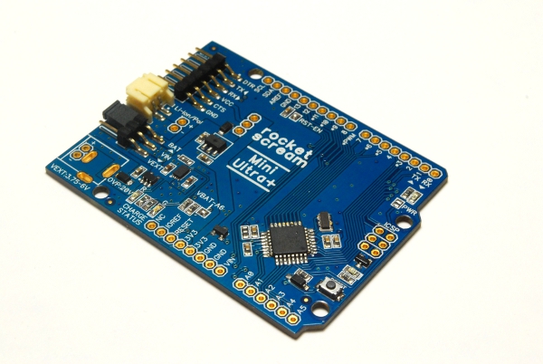
Some of you might come across our first attempt on making a low power Arduino compatible board here. That was 2 years ago (time sure flies)! Well we thought it would be great if the board gets a little revamp and some tweaking so that it’s power consumption is comparable to our Mini Ultra 8 MHz!
Simplifying the initial design was our main objective. Having an all in one (high voltage buck converter, dual source battery charger) power management integrated circuit in the original design sounds kinda cool. But, this comes with a price and a pretty much high quiescent current of nearly 50 μA! Throughout the years of making boards for low power applications, we never really have to use the USB functionality of the board. It seems rather redundant when you are going to use them somewhere remote for long time and deeply embedded applications. Having these few restriction of the design specifications, the Mini Ultra 8 MHz + is born!
Some of the specifications of Mini Ultra 8 MHz +:
- Microcontroller: ATMega328P-AU:
- We used them a lot in our designs and their recent price seems to be a plus point (USD1.73 @ 100 pieces quantity).
- Compatible with Arduino Pro 8 MHz 3.3 V.
- Low power consumption:
- The design is based on Mini Ultra 8 MHz but a charging circuitry is added. Up to 500 mA charging capability is available. The DFN-8 package was chosen for better heat dissipation.
- Total power down current is estimated to be below 10 µA (8.8 µA measured).
- On board monitoring:
- Battery level monitoring using analog input pin A6.
- Temperature monitoring (MCP9700) using analog pin A7:
- MCP9700 consumes about 6 µA!
- Protection:
- Reverse voltage protection on external voltage input.
- Over voltage protection up to 20 V.
- Form factor:
- Compatible with classic Arduino Uno & Arduino Duemilanove.
- Uses latest pin out as in Arduino Uno R3.
- LED:
- Power LED (can be disable through solder jumper).
- Buffered user LED on pin D13.
- Charging status LED.
In the design process, some features were considered (some mentioned above) but were not included in the final version:
- A buck-boost converter instead of LDO:
- We are big fan of switching regulator. The initial design of Ultra were based on a buck-boost converter. However, buck-boost converter usually draws around 25 µA – 50 µA even at light load operation. We had used several parts like LTC3441 and TPS63001 in the past. They are awesome for certain application and situation. For example, you will find them very suitable if you need to power a radio transceiver that consumes 300 mA during transmission but probably only need them to last 6-12 months.
- On board Real Time Clock (RTC):
- We feel that not all low power application requires a clock. Depending on the application, the on-chip watchdog timer on the ATMega328P-AU can be used to wake the microcontroller up but if you need a full blown RTC functionality, you can always add them through a shield.
- On board logging memory:
- The thought of adding a micro SD slot or a serial flash memory was very tempting. However, similar to the RTC feature, not all application requires them and adding them will increase the total cost. Furthermore, the on-chip 1 kB of EEPROM could be just enough for small logging application.
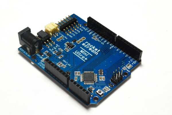
We are currently verifying and testing the design. The board will either come without the headers or with the headers installed.
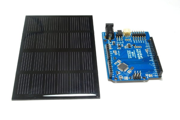
Now, time to test the Mini Ultra 8 MHz Plus with the solar panel! Unfortunately, it has been gloomy for the past few weeks…
Take care and happy tinkering!


Leave a Reply
Want to join the discussion?Feel free to contribute!