Mini Ultra 8 MHz – Current Consumption (Part 1)
At first, we thought of putting the current consumption measurement process of Mini Ultra MHz in one post. However, the post seems to be too long to be fitted into one post. So, here is the 1st part of the current measurement process.
One of the most challenging task of designing a very low power board is selecting proper and suitable components. At the initial point of design process, we must set a target of current consumption that we wanted to achieve on the design. On the Mini Ultra 8 MHz, we have set a reasonable target of below 5 µA during sleep mode. We know the ATmega328P is capable of going down all the way to 0.1 µA during power down mode. A room of 4.9 µA seems to be a quite large number. We wanted the Mini Ultra to run at 3.3 V at 8 MHz as more and more integrated circuits, modules, and devices are running at 3.3 V or even lower (1.8 V). But, this requires a proper voltage regulation on the board which will contribute to the overall board quiescent current. This explain why we have a working room of 4.9 µA in our design. Choosing a suitable voltage regulator is very important in the design. Some of the voltage regulator requirements that we were looking for:
- Low quiescent current:
- The amount of current required to maintain the output voltage of the regulator must be minimal during no load or light operation of the board.
- Reasonable maximum output current:
- We wanted the regulator to have a reasonable maximum output current to support possible external peripherals and devices (for example: sensors, communication interface, data logging). This requirement is usually affected by the quiescent current criteria mentioned above. We set a reasonable 150 mA to 300 mA range for this board design.
- Suitable for battery input voltage range.
- Low dropout voltage:
- Running the board using battery means that the amount of voltage drop that takes place in the voltage regulator must be minimal to maximize the usage of the battery usable voltage range. We plan to use Li-Ion or Li-Pol battery pack that has minimum usable voltage range around 3.4 V. For the board to run at 3.3 V, we can afford to have a drop of 100 mV only at the bottom range of the usable battery voltage range. Therefore, we set a dropout voltage range of 100 mV to 200 mV.
- Fixed output voltage:
- We wanted the 3.3 V level to be as precise and accurate as possible. Using adjustable version of voltage regulator (usually using a pair of resistors), will introduce more deviation and also requires more board space.
- Small package:
- The Mini Ultra as the name suggest, is targeted to have a very small dimension. Smaller voltage regulator packages such as SOT23, DFN6, and SOT23-5 are more suitable in this case.
Based on the above requirements and after spending some time on few semiconductor website, the selection came down to 2 possible candidate, TPS78233 and MCP1700T-3302E. Here are the comparison for several aspect we are looking at:
| Specifications | TPS78233 | MCP1700T-3302E |
| Maximum Output Current, IL | 150 mA | 250 mA |
| Dropout Voltage, VDR | 130 mV @ IL = 150 mA | 178 mV @ IL = 250 mA |
| Input Quiescent Current, IQ | 0.5 μA | 1.6 μA |
| Package | TSOT23-5 | SOT23 |
| Manufacturer | Texas Instruments | Microchip Technology |
| Cost 1 k Units | USD 0.25 | USD 0.27 |
We chose Microchip’s MCP1700T-3302E at the end based on our experience that the extra 100 mA of output might be very handy when interfacing with external peripherals. Furthermore, a difference of 1.1 μA of quiescent current between them is still rather acceptable in this particular case. On the dropout voltage, I guess it would be unfair to compare them at different load current. Both are having pretty tiny packages and price wise they are both below USD 0.30 for 1 k quantity purchase.
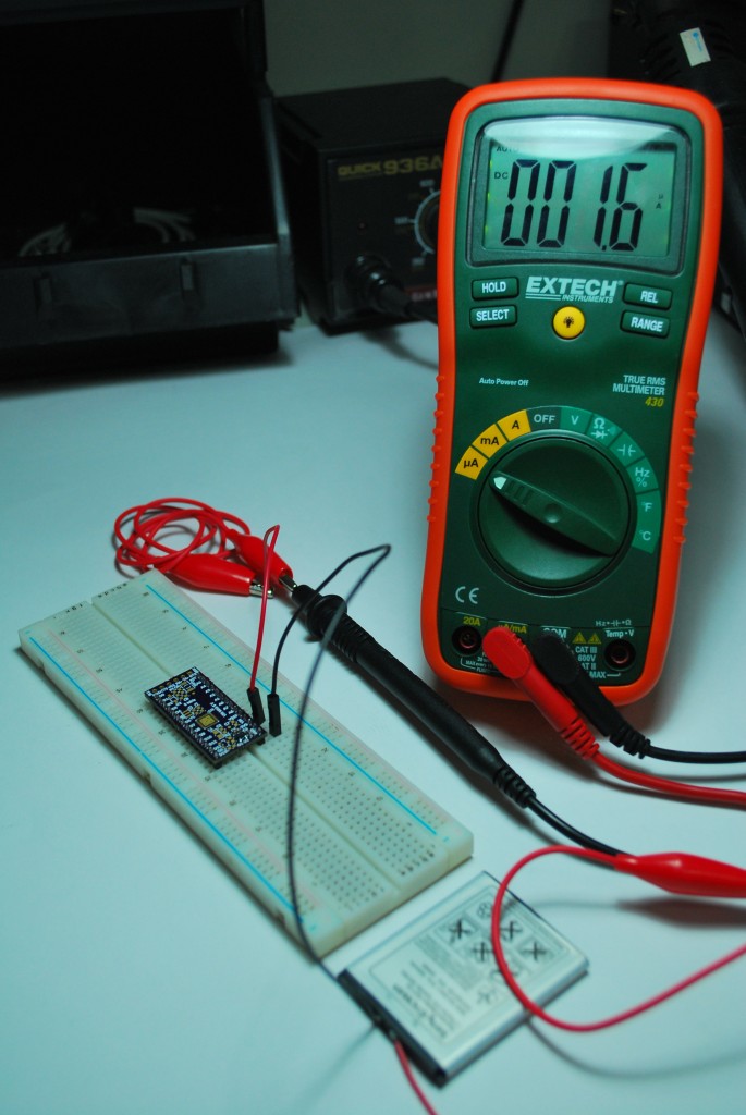
The MCP1700T-3302E requires only 2 ceramic capacitors (at the input & output pins) of 1 μF to operate. This lowers the overall board cost by eliminating the need of using tantalum capacitor especially found in older and earlier LDO design. The moment we got our hands on the MCP1700T-3302E, we solder them onto the Mini Ultra board without any other components to check the quiescent current of the regulator except the 2 decoupling capacitors. We use a Li-Polymer battery to power up the board with a measured voltage of 4.0 V. Below is the setup we used to measure the quiescent current of MCP1700T-3302E on the Mini Ultra board:
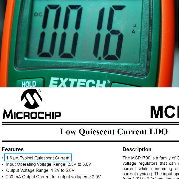
The result obtained is exactly what is stated in the datasheet and we are pretty please with this. We used an Extech EX430 true RMS multimeter for this purpose (after reading the good review on EX330 by Dave Jones).
Stay tune for the next part of this post which covers the overall Mini Ultra 8 MHz board current consumption. There will be some Arduino codes involved to get the board all the way down to μA range. Now, we have to get back to more test and measurement. 🙂



See also the low power series on the JeeLabs weblog – based on a JeeNode which is using exactly the same components – http://jeelabs.org/tag/lowpower/.
Jean,
We followed your work on the JeeNode and the rest of the supporting software too. 🙂
Hi,
I know this post was in 2011. In 2013, Microchip has a new component, the MCP1710 and has Ultra-Low 20 nA (typical) Quiescent Current @ 200mA.
The package is not very interesting for DIY it’s a 8 pin VDFN.
thanks for the awesome post.
Hi Jerome,
Saw that chip some time ago, the only drawback is the higher drop voltage and the smaller output current. VDFN is cool because heat dissipation is awesome.