Mini Ultra 8 MHz (Low Power Arduino Compatible Board) – Introduction
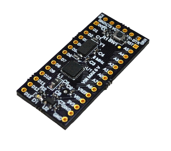
Some of you might have came across our earlier design on low power Arduino compatible board going under the name Ultra. We are making a tiny version of the Ultra design – Mini Ultra 8 MHz. Mini Ultra 8 MHz is a simplified and stripped down version of Ultra. Using this board under the Arduino IDE, you can select the board as “Arduino Pro or Pro Mini (3.3 V 8 MHz) w/ ATmega328”. As the name suggest, Mini Ultra 8 MHz is designed to be low power (less than 5 µA in power down mode).
Some preliminary features of Mini Ultra 8 MHz:
- 3.3 V operation.
- 8 MHz crystal (final revision using ceramic resonator).
- ATmega328P in QFN32 package.
- Ultra low power regulator with 1.6 µA quiescent current and output current of 250 mA (100 mA more than Arduino Pro Mini!).
- 28 pins 600 mil wide package pin out.
- All digital IO pins (D0 – D13) are broken out to one side of the board.
- All analog pins (A0 – A7 (Yes 2 extra analog pins!)) are broken out to one side of the board.
- Analog power supply filter circuitry as recommended by Atmel®.
- Reset pin equipped with recommended circuitry by Atmel® for noisy environment usage.
- Pin D13 connection to indication LED is through a transistor to avoid loading issue when using pin D13 as input.
- 6 pins FTDI header for sketches uploading from Arduino IDE.
- Maximum 6 V power input voltage – Suitable for battery operated.
- Dimension – 18.41 mm x 39.37 mm (6.37 mm longer than Arduino Pro Mini).
At time of writing, 2nd prototype version of the board is already on shipment and will arrive anytime in the week. This will be the final testing version before we produce in bigger batch. The 1st prototype uses 0402 components and uses a larger 6035 SMD 8 MHz crystal. The significant changes found on the 2nd prototype includes replacement of 0402 components with 0603 components and using a ceramic resonator with built in capacitor. Design files will be posted once the board is out for sale.
Currently we are testing the board on all aspect especially the power consumption during power down mode. The bootloader was burned into the fresh ATmega328 chip using AVRISP mkII. Once the bootloder reside in the ATmega328, we tried loading the “Blink” program using the setup shown below:

Uploading sketches to the Mini Ultra 8 MHz using FTDI FT232
On the left is a custom Rocket Scream FT232 breakout board to upload the sketches from the Arduino IDE. The Mini Ultra 8 MHz sits on the breadboard with DTR, RXD, TXD and GND connected to the FT232 breakout board through male-to-female jumper wires. On the right is the Arduino Uno. We use it as a power supply source to the Mini Ultra 8 MHz board by using male-to-male jumper wires on the 5 V and GND line. Yes, we envy those guys that can afford those expensive desktop variable power supply! Uploading the sketch is successful at 1st attempt!

Blinky hello world!
Before we go back to work (more and more test!) on the Mini Ultra, here’s a snapshot on Arduino Uno sitting side by side with Ultra and Mini Ultra 8 MHz.

Arduino Uno, Ultra and Mini Ultra 8 MHz


this is an excellent board, beautiful.
is possible fusion this 2 modules (from sparkfun) into one?
sku: DEV-09873. FTDI Basic Breakout – 3.3V
sku: PRT-10401. LiPo Charger Basic – Mini-USB
to power with battery would be better work with 150 mA power regulator, because battery project are often very low power.
Giancarlo,
We already released this board some time ago and it’s up for sale on the website. We put a provision for 250 mA as different application might need different current. But, you’ll probably need to shut the external peripheral down in any of the cases (150mA or 250mA) to conserve energy. We are working on charger at the moment. We didn’t include them as some people might just power them using a non-rechargeable batteries. So, it doesn’t add the cost in that case.
I have a question. I can take analog pin A0 and A1 as digital Outputs when I set
pinMode(A0, OUTPUT);
digitalWrite(14, HIGH);
But I can’t acces A6 and A7 in the same way.
Can I use them as Digital Out Ports anyway?
Pin A6 & A7 are pure analog input pins.
I tried to take it as analog input and it works perfectly, so I only change my analog Inputs to A6 and A7 and take A0 and A1 as digital Outputs.
That solves my problem.
But can u tell me if this is because of the Hardware or of the libraries.
I’m very curious.
This is due to the ATMega328P chip itself. Not sure why Atmel did that. Probably to shave off a little bit of cost. 🙂
OK. Thank you.