Mini Ultra 8 MHz – Current Consumption (Part 2)
This is the second part of current consumption measurement of Mini Ultra 8 MHz. We’ll show some important steps to put the board into very low power state. The result is well beyond our expectation and we are pretty excited as this marks the completion of one of the main objective of the design.
It has been a pretty hectic but a fruitful weekend. Over the weekend, works on the PID control of the reflow oven controller has progressed extremely well (thank you Brett for helping out) and now we get to complete the testing on Mini Ultra 8 MHz.
Back to where we left in the first part of the current consumption measurement, we soldered the remaining components onto the board. We are using a new revision of the board (yes, it went through 3 cycles already!) which has a ceramic resonator with built-in capacitor which saves board space with a reasonable 0.5% accuracy. Here’s a snapshot of the fully assembled board. At the moment of writing this, the board went for the 4th and final revision. 🙂

The board is preloaded with Arduino Pro Mini 8 MHz bootloader with modified extended fuses. The only differences is the Brown Out Detect (BOD) fuse which we disabled completely for this purpose of testing. This is done easily by changing line 11 (snapshot below) in the hardware/arduino/boards.txt file from 0x05 to 0x07. The BOD settings explanation can be found on page 298 of the ATmega328P datasheet and you can use a very handyAVR fuse calculator here. Keep in mind that with the BOD feature enabled, there will an extra of 20 µA current consumed during power down mode. The BOD can also be changed on the fly through software control but it will require strict timing which we will cover in another post. For this testing purpose, we’ll use the fuse setting to disable the BOD.
##############################################################

pro328.name=Arduino Pro or Pro Mini (3.3V, 8 MHz) w/ ATmega328

pro328.upload.protocol=stk500
pro328.upload.maximum_size=30720
pro328.upload.speed=57600

pro328.bootloader.low_fuses=0xFF
pro328.bootloader.high_fuses=0xDA
pro328.bootloader.extended_fuses=0x05
pro328.bootloader.path=atmega
pro328.bootloader.file=ATmegaBOOT_168_atmega328_pro_8MHz.hex
pro328.bootloader.unlock_bits=0x3F
pro328.bootloader.lock_bits=0x0F

pro328.build.mcu=atmega328p
pro328.build.f_cpu=8000000L
pro328.build.core=arduino

##############################################################
Once the bootloader is loaded, it’s time to write some code to enable the board to go into power down mode. The ATmega328P can be put into 6 different type of sleep modes. Each sleep mode has different power consumption, active clocks, and wake up sources. We’ll be putting the microcontroller into power down mode in this case. The microcontroller can be waken up through external interrupt, TWI address match, and watchdog timer (we’ll do a series of tutorials and examples on how to use them pretty soon) in this mode. Here’s the code used to put the Mini Ultra 8 MHz into power down mode.
// **** INCLUDES *****
#include <avr/sleep.h>
#include <avr/power.h>
// ***** CONSTANT *****
#define MAX_PIN_COUNT 22    // Digital IO 0-13, Analog A0-A7

void setup()
{
    uint8_t pin;

    // Put all pins into output mode and low state
    for (pin = 0; pin < MAX_PIN_COUNT; pin++)
    {
        pinMode(pin,OUTPUT);
        digitalWrite(pin,LOW);
    }

    // Set sleep mode
    set_sleep_mode(SLEEP_MODE_PWR_DOWN);
    // Enable sleep mode
    sleep_enable();
    // Disable ADC, must be done before calling
    // power_all_disable() as to disable ADC,
    // clock is required
    // Refer to datasheet page 45
    ADCSRA &= ~(1 << ADEN);
    // Disable all peripheral power
    power_all_disable();
    // Enter sleep mode
    sleep_mode();
}

void loop()
{
    // Zzz...
}
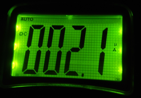
The above code basically puts the microcontroller into power down mode and shutting down all peripherals. Special treatment is required for the ADC module as it must be disabled before shutting it down. Once the code is loaded onto the board we perform the current measurement using the setup below. We managed to get the current consumption of the board down to 2.1 µA. At the beginning of the design, we have set a target of 5 µA, but the end result is pretty amazing. The ATmega328P is basically consuming only 0.5 µA (2.1 – 1.6 µA) as the on board regulator consumes the remaining about 1.6 µA (refer to our previous post). We’ll be giving some examples soon on waking up the board to perform certain task (sensor reading, data transmission, data logging) before going into power down mode again. Plans for a small power management library (sort of wrapper functions with wake up source selection and power down duration) is in the pipeline and we hope can finish that while the boards go for first batch of production.

Take care and happy tinkering.


Hi,
Can this being adapted for 328p? I try to save so much power as possible.. this far reached 800uA. 328p is locating in breadboard, 5V voltage (5V needed to run relays when not sleeping). How about using 2MHz crystal?
BR, Kari
Finland
Hi Kari,
We are using the same chip with different package. Few possible reasons that your consumption is higher:
– You are running at 5V
– Is your brownout detector disable?
– If you are using a 5V regulator that is not low in quiescent current, that might be the most possible reason
You can check out our low power library for ATMega328P:
http://www.rocketscream.com/blog/2011/07/04/lightweight-low-power-arduino-library
Hi Admin,
Thanks for your reply.
I loaded you LowPower.h and LowPower.cpp, and now I succeed to reach 450uA with external PD 2 wake-up. Call is
attachInterrupt(0, wakeUpNow, LOW);
LowPower.powerDown(SLEEP_FOREVER, ADC_OFF, BOD_OFF);
And this works fine!
Additional, when powering the MCU I read values of pins PD3 and PD5 (mechanical switches, those are defining the code flow in application. There are guideline to use 10k pull-down resistors, but this increases the power consumptionn 300-400uA per pin. I replaced 10k’s with 1M resistors, and the device is working properly with the larger resistors, and the power need is not rising from 450uA. Can I use 1Megs resistors as pull-downs without any harm to the 328p?
Furhermore, I would like to reduce the power consumption… Your example
LowPower.powerDown(SLEEP_8S, ADC_OFF, BOD_OFF);
takes only 6.4uA.
Please reply, if you have any hint or advice.
I found your LowPower libraty extremely usefull, many thanks for sharing the knowledge; great job!
BR, Kari Stachon, Finland
Hi Kari,
Using 1M is fine as long as you are able to sink it when the high voltage is present. 1M is considered as a weak pull down in this case. I usually use 100K most of the time.
In the example you have mentioned, the clock to the IO is basically cut-off by the MCU. On top of that, I didn’t enable the external interrupt and it is supposed to wake up using the WDT (8 seconds). The board I used have a regulator that consumes about 1.6uA. Together with the WDT on (8 seconds), it comes to be around ~5.6uA. The IO pins didn’t consume any noticeable current in this case.
How did you power your MCU (the 5V)?
Hi Admin,
I use laboratory DC power supply HY3003, no regulator; I just tried with ordinary 4.5 volt battery, same result (450uA at sleep mode). It seems that hardware wakeup mode (wakeup when PD2 is open from +5) takes that 400uA – for some reason.. Maybe some IO devices or something are still running in LowPower.powerDown(SLEEP_FOREVER, ADC_OFF, BOD_OFF) mode?
Strange, because LowPower.powerDown(SLEEP_8S, ADC_OFF, BOD_OFF) takes <10uA as mentioned.
BR, Kari Stachon
..continued
I just tested your example program (pinwakeup), and the power consumption was round 5uA!
So there is something totally wrong in my main code, I add it here, but I dont assume that you have time to check it out. The power need in sleep mode is 450uA righ after the first sleep call.
BR, Kari
#include
#include
#include “avr/LowPower.h”
#define DELAYLED 13 // LED for exit and entry delay //
#define GSM 12 // GSM alarm box (LED when active)
#define SIREN 11 // Siren (LED when active)
#define DELAYPIN 3 // Delay Switch pin
#define ALLWAYSGSMALARM 5 // Allways GSM alarm pin
#define GSMOnTime 180 // GSM device ON time secs
#define SIRENOnTime 45 // Siren ON time secs if alarm occurs
#define SirenBeebTime 0.3 // Siren beeb time secs on exit and entry
#define SirenBeepRounds 2 // Siren Beep rounds
#define ExitDelay 20 // Exit and entry delay 15, if DELAYPIN Open
// If DELAYPIN is OC (open), Exit delay is same as Entry Delay
// If DELAYPIN is Closed, Exitdelay and entrydelay are 2 * defined ExitDelay
// In application, here is a mechanical scwitch (on DELAYPIN, 3)
volatile boolean StartUp = true;
volatile boolean EntryDelay = false;
volatile boolean AlarmState = true;
volatile unsigned int DelayRounds = 0;
volatile unsigned ExitDelayTime; // Exit delay time secs
volatile unsigned EntryDelayTime; // Entry delay time
const int wakePin = 2; // pin used for waking up
int sleepStatus = 0; // variable to store a request for sleep
int count = 0; // counter
int DelayState = 0;
void wakeUpNow() // here the interrupt is handled after wakeup
{
// No operations here
}
void setup()
{
//Serial.begin(9600); // for degug
pinMode(wakePin, INPUT);
pinMode(DELAYLED, OUTPUT);
pinMode(GSM, OUTPUT);
pinMode(SIREN, OUTPUT);
pinMode(DELAYPIN, INPUT);
pinMode(ALLWAYSGSMALARM, INPUT);
StartUp = true;
EntryDelay = true;
DelayState = digitalRead(DELAYPIN);
AlarmState = digitalRead(ALLWAYSGSMALARM);
//Serial.println(DelayState);
digitalWrite(DELAYLED, false); // set the LED off
digitalWrite(GSM, false); // set the LED off
digitalWrite(SIREN, false); // set the LED off
if (DelayState==0)
{
ExitDelayTime = ExitDelay;
EntryDelayTime = ExitDelay;
}
else
{
ExitDelayTime = int(ExitDelay * 2);
EntryDelayTime = int(ExitDelay * 2);
}
/* Now it is time to enable an interrupt. In the function call
* attachInterrupt(A, B, C)
* A can be either 0 or 1 for interrupts on pin 2 or 3.
*
* B Name of a function you want to execute while in interrupt A.
*
* C Trigger mode of the interrupt pin. can be:
* LOW a low level trigger
* CHANGE a change in level trigger
* RISING a rising edge of a level trigger
* FALLING a falling edge of a level trigger
*
* In all but the IDLE sleep modes only LOW can be used.
*/
// attachInterrupt(0, wakeUpNow, LOW); // use interrupt 0 (pin 2) and run function
// wakeUpNow when pin 2 gets LOW
}
/* void sleepNow() // here we put the arduino to sleep
{
/* Now is the time to set the sleep mode. In the Atmega8 datasheet
* http://www.atmel.com/dyn/resources/prod_documents/doc2486.pdf on page 35
* there is a list of sleep modes which explains which clocks and
* wake up sources are available in which sleep mode.
*
* In the avr/sleep.h file, the call names of these sleep modes are to be found:
*
* The 5 different modes are:
* SLEEP_MODE_IDLE -the least power savings
* SLEEP_MODE_ADC
* SLEEP_MODE_PWR_SAVE
* SLEEP_MODE_STANDBY
* SLEEP_MODE_PWR_DOWN -the most power savings
*
* For now, we want as much power savings as possible, so we
* choose the according
* sleep mode: SLEEP_MODE_PWR_DOWN
*
*/
/*
digitalWrite(DELAYLED, false); // set the LED off
digitalWrite(GSM, false); // set the LED off
digitalWrite(SIREN, false); // set the LED off
set_sleep_mode(SLEEP_MODE_PWR_DOWN); // sleep mode is set here
sleep_enable(); // enables the sleep bit in the mcucr register
// so sleep is possible. just a safety pin
/* Now it is time to enable an interrupt. We do it here so an
* accidentally pushed interrupt button doesn’t interrupt
* our running program. if you want to be able to run
* interrupt code besides the sleep function, place it in
* setup() for example.
*
* In the function call attachInterrupt(A, B, C)
* A can be either 0 or 1 for interrupts on pin 2 or 3.
*
* B Name of a function you want to execute at interrupt for A.
*
* C Trigger mode of the interrupt pin. can be:
* LOW a low level triggers
* CHANGE a change in level triggers
* RISING a rising edge of a level triggers
* FALLING a falling edge of a level triggers
*
* In all but the IDLE sleep modes only LOW can be used.
*/
/*
attachInterrupt(0,wakeUpNow, LOW); // use interrupt 0 (pin 2) and run function
// wakeUpNow when pin 2 gets LOW
sleep_mode(); // here the device is actually put to sleep!!
// THE PROGRAM CONTINUES FROM HERE AFTER WAKING UP
sleep_disable(); // first thing after waking from sleep:
// disable sleep…
detachInterrupt(0); // disables interrupt 0 on pin 2 so the
// wakeUpNow code will not be executed
// during normal running time.
} */
void loop()
{
// First phase after startup: layhch exit delay
if (StartUp==true)
{
Siren(SirenBeebTime, SirenBeepRounds); // Siren on
BlinkDelay(ExitDelayTime, 0); // Exit delay secs
StartUp=false; // StartUp false = system armed, waiting for Entry
//Serial.println(“nukkuu..”);
attachInterrupt(0, wakeUpNow, LOW); // sleep function called here = goto sleep mode
LowPower.powerDown(SLEEP_FOREVER, ADC_OFF, BOD_OFF);
detachInterrupt(0);
}
if (EntryDelay == true) // Entry – Siren on for 1 sec, gsm-device on, blink on
{
Siren(SirenBeebTime, SirenBeepRounds); // Siren on
BlinkDelay(EntryDelayTime, 0); // Entry delay for DelayRounds secs
EntryDelay=false; // System Armed for Alarm
}
digitalWrite(SIREN, true);
digitalWrite(GSM, true);
for (float i=0; iSIRENOnTime)
{
digitalWrite(SIREN, false);
}
if (i/10 == int(i/10) && AlarmState==true)
{
BlinkDelay(1, 1); // Blink exit/entry led, and relay for gsm
}
}
digitalWrite(GSM, false);
EntryDelay = true;
//Serial.println(“nukkuu..”);
attachInterrupt(0, wakeUpNow, LOW); // sleep function called here = goto sleep mode
LowPower.powerDown(SLEEP_FOREVER, ADC_OFF, BOD_OFF);
detachInterrupt(0);
//sleepNow();
}
void Siren(float sec, int repeat)
{
for (int i=0; i<repeat; i++)
{
digitalWrite(SIREN, true); // Siren on for sec Seconds
delay(sec*1000);
digitalWrite(SIREN, false); // Siren off
delay(300);
}
}
void BlinkDelay(int sec, int gsmtrigger)
{
if (gsmtrigger == 0)
{
for (int i=0; i<sec; i++)
{
digitalWrite(DELAYLED, true);
delay(500);
digitalWrite(DELAYLED, false);
delay(500);
}
}
else
{
digitalWrite(DELAYLED, true);
delay(1000);
digitalWrite(DELAYLED, false);
}
}
Hi Admin,
Ignore previous code, here is a refined version. But still: 450uA.
BR, Kari
#include “avr/LowPower.h”
#define DELAYLED 13 // LED for exit and entry delay //
#define GSM 12 // GSM alarm box (LED when active)
#define SIREN 11 // Siren (LED when active)
#define DELAYPIN 3 // Delay Switch pin
#define ALLWAYSGSMALARM 5 // Allways GSM alarm pin
#define GSMOnTime 20 // GSM device ON time secs
#define SIRENOnTime 15 // Siren ON time secs if alarm occurs
#define SirenBeebTime 0.3 // Siren beeb time secs on exit and entry
#define SirenBeepRounds 2 // Siren Beep rounds
#define ExitDelay 10 // Exit and entry delay 15, if DELAYPIN Open
// If DELAYPIN is OC (open), Exit delay is same as Entry Delay
// If DELAYPIN is Closed, Exitdelay and entrydelay are 2 * defined ExitDelay
// In application, here is a mechanical scwitch (on DELAYPIN, 3)
volatile boolean StartUp = true;
volatile boolean EntryDelay = false;
volatile boolean AlarmState = true;
volatile unsigned int DelayRounds = 0;
volatile unsigned ExitDelayTime; // Exit delay time secs
volatile unsigned EntryDelayTime; // Entry delay time
const int wakeUpPin = 2; // pin used for waking up
int sleepStatus = 0; // variable to store a request for sleep
int count = 0; // counter
int DelayState = 0;
void wakeUp() // here the interrupt is handled after wakeup
{
// No operations here
}
void setup()
{
//Serial.begin(9600); // for degug
pinMode(wakeUpPin, INPUT);
pinMode(DELAYLED, OUTPUT);
pinMode(GSM, OUTPUT);
pinMode(SIREN, OUTPUT);
pinMode(DELAYPIN, INPUT);
pinMode(ALLWAYSGSMALARM, INPUT);
StartUp = true;
EntryDelay = true;
DelayState = digitalRead(DELAYPIN);
AlarmState = digitalRead(ALLWAYSGSMALARM);
//Serial.println(DelayState);
digitalWrite(DELAYLED, false); // set the LED off
digitalWrite(GSM, false); // set the LED off
digitalWrite(SIREN, false); // set the LED off
if (DelayState==0)
{
ExitDelayTime = ExitDelay;
EntryDelayTime = ExitDelay;
}
else
{
ExitDelayTime = int(ExitDelay * 2);
EntryDelayTime = int(ExitDelay * 2);
}
}
void loop()
{
// First phase after startup: layhch exit delay
if (StartUp==true)
{
Siren(SirenBeebTime, SirenBeepRounds); // Siren on
BlinkDelay(ExitDelayTime, 0); // Exit delay secs
StartUp=false; // StartUp false = system armed, waiting for Entry
//Serial.println(“nukkuu..”);
attachInterrupt(0, wakeUp, LOW); // sleep function called here = goto sleep mode
LowPower.powerDown(SLEEP_FOREVER, ADC_OFF, BOD_OFF);
detachInterrupt(0);
if (EntryDelay == true) // Entry – Siren on for 1 sec, gsm-device on, blink on
{
Siren(SirenBeebTime, SirenBeepRounds); // Siren on
BlinkDelay(EntryDelayTime, 0); // Entry delay for DelayRounds secs
EntryDelay=false; // System Armed for Alarm
}
digitalWrite(SIREN, true);
digitalWrite(GSM, true);
for (float i=0; iSIRENOnTime)
{
digitalWrite(SIREN, false);
}
if (i/10 == int(i/10) && AlarmState==true)
{
BlinkDelay(1, 1); // Blink exit/entry led, and relay for gsm
}
}
digitalWrite(GSM, false);
EntryDelay = true;
StartUp = true;
}
}
void Siren(float sec, int repeat)
{
for (int i=0; i<repeat; i++)
{
digitalWrite(SIREN, true); // Siren on for sec Seconds
delay(sec*1000);
digitalWrite(SIREN, false); // Siren off
delay(300);
}
}
void BlinkDelay(int sec, int gsmtrigger)
{
if (gsmtrigger == 0)
{
for (int i=0; i<sec; i++)
{
digitalWrite(DELAYLED, true);
delay(500);
digitalWrite(DELAYLED, false);
delay(500);
}
}
else
{
digitalWrite(DELAYLED, true);
delay(1000);
digitalWrite(DELAYLED, false);
}
}
I think it might have to do with DELAYPIN state. Try masking them out 1st. Other than that, I think the other code section most probably has nothing to do with the power.
Than you for the hint.
The root cause was not DELAYPIN, but one forgotten test-pull-down-resistor 10k between IC pin 7 (VCC) and ground… OMG! (I soldered 1Megs resistors to the connector, but leaved 10k’s still there, then I turned the connector 90 degrees, and vola: I had an extra resistor between +5 and ground. Shit happenes..
Anyway, now the power is 13.7uA, very good! And all the functionality I need.
Once again, thank you for helping me, and for LowPower lib.
Kari
Hello Kari,
Glad to help and very happy it work for you! If you have a blog or something, do let us know. Will be glad to know about it! Thank you.
Hi again Admin!
I have worked on a project “battery running gsm-alarm” (project of my own:)
Goal was a battery-based gsm-alarm system. No big deal – BUT. No battery
running gsm-alarm systems available on market! (At least in Europe). They all want 12 or9 VDC from wall. Of coarse, several hours back-up battery is included in the
commercial solutions. No use at all, when you have no grid power.
But what is needeed, is a system that stays alive for 1-2 years with just
a battery, and when PIR signals is activates gsm-alarm also. I have done that.
Queiscient current with PIR is round 160 uA.
Just one question… How I protect the Intel hex code in 328p? There is
lock bytes, yes, how can I set the lock with avrdude? Stupid question, I
assume, but I try the find the easiest way to handle this matter.
If you want a photo or something like that, please give an e-mail (the
pictures I took are allmost 3-4 GB).
Yours Sincerely, Kari
Hi Kari,
Your total quiescent of 160 uA really amazed me because it has so many components on top of the microcontroller. A typical off the rack system would probably last few hours only. Yours is awesome! It even has commercial values. 🙂
To lock the flash using avrdude, if I recall it correctly, the command is something like this: -U lock:w::m where the 0xHH is the lock bits value (it’s different for different ATMega).
I’ll drop you a mail after this! Thank you again for the information. I think it’s worth sharing with everyone. 🙂
Hi
I am using Pro mini ATMEGA328 with HMC5983. I would like to have external interrupt to use watchdog function from HMC5983 input. Could you please tell me what t do step by step?
1. Connection of DRDY pin
2. Its Micro coding
Hi Kamran,
Question like this is better if posted on the forum.