Vehicle Tracking & Logging Using TraLog Shield
Last week when we posted an update to the WISMO228 library for Arduino, we mentioned we were using the TraLog shield as a vehicle tracking & logging device. We finally found some time in between everything to write this post and illustrate what the TraLog shield is capable of.
Years back, when we were doing a freelance job making a tea brewer machine, the client asked whether we were interested in making a vehicle tracking device for oil tankers in Indonesia. The job was beyond our capability to accept. There were critical safety aspects (oil & gas = explosion proof) and most importantly deploying them on thousands of oil tankers in a large country like Indonesia would be a big task (scary too!). We politely declined the offer (and finished the tea brewing machine). But soon after that, we started to toy around with the idea of actually making one! That is basically how the TraLog shield came about.
In this example, the TraLog shield is used to track the position of a vehicle using GPS, transmits the position to a server (Cosm/Pachube in this case) and also stores the position in non-volatile memory. Hardware requirements:
- An Arduino board – A Duemilanove or Uno.
- TraLog shield (with included GSM and GPS antennas) – Of course!
- Micro SD card – Pre-formatted in FAT32 format.
- Car power adapter to DC barrel jack – Ensure the internal fuse rating is capable of at least 2 A.
- SIM card – Not pin locked and capable of data transfer.
- Laptop – If you want see what’s happening in the background.
- 2 CR1220 3 V coin cell – If you want to maintain the RTC and GPS hot start capability in the even of power failure.

As the GSM module requires nearly 2 A of peak current during transmission, the power from the USB port can’t provide enough current. The TraLog shield houses an efficient switch mode buck converter which is capable of taking in a higher input voltage like 12 V and regulating it down to 3.6 V (voltage input for the GSM module) without generating a lot of heat like a conventional linear regulator. We were looking for a car adapter plug that has a DC barrel jack plug on the other end to power the system but we couldn’t find any nearby and buying from Ebay would have meant waiting a lot longer. We ended up buying the cheapest car charger cable we could find that came with a micro USB end (for your fancy cell phones). We ripped off the micro USB end and replaced it with DC barrel jack cut from from an old transformer based AC-DC adapter. As expected, the car charger cable comes with a MC34063 buck circuit which we removed and connected directly to the fuse section (rated 2.5 A).


Once we got the all the power requirements sorted out, we were basically left with putting everything else together. The TraLog shield stacked on top of an Arduino board was placed on the dashboard (with a double sided tape) with the GPS active antenna placed next to it. You don’t have to put the GPS antenna outside the vehicle (like on the roof top) as it works awesomely inside the vehicle. If the GPS gets a proper satellite signal fix, the red LED will start to blink every 1 s. We usually get around a 7-8 satellite signal fix with a few more in sight (but not fixed) with the antenna placed inside the vehicle.

We used a laptop to monitor the operation of the system. We used hyper terminal (old school rocks!) but any simple terminal program will do. You can skip this if you think it’s going to be a big distraction to your driving!

The Arduino sketch (available for download at the bottom of the post) basically performs a GPS coordinate acquisition every minute (depending how much granularity you need and the cost of GPRS data transmission), transmits the location (longitude & latitude) on GPRS as Cosm feeds, and logs the location and time onto the micro SD card. Sending the coordinates to the Cosm server utilizes a HTTP PUT request implemented by the WISMO228 library. The sketch can be easily modified to send the data to another server (with custom scripts) using either the HTTP PUT or the insecure HTTP GET method provided in the library. The unused I2C and analog pins on the Arduino board can also be used to interface with external sensors (temperature, barometric, pressure, etc) on top of the GPS coordinates.
if (millis() > scheduler)
{
  // Set next logging interval
  scheduler = millis() + LOG_INTERVAL;

  // Check for new GPS data
  processGPS();

  // If new GPS data is available
  if (newGpsData)
  {
    // Send latest latitude & longitude to Cosm
    processGSM();
    // Log latitude, longitude, and time onto micro SD card
    processSD();
    // Latest GPS data logged
    newGpsData = false;
  }
}
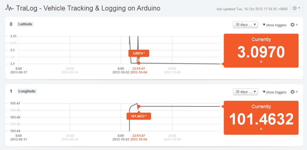
We created a Cosm feed here which has a latitude and longitude data stream. Without graphical geo location mapping, it would be very hard to visualize the movement of the system. Cosm provides a simple geo-location mapping utility called Trails that can be placed on any regular website. However we found several limitations:
- The data points selected from the feeds are spaced out and hence produce jagged way points on the map.
- Only the last 24 hours of data is mapped.
But, it gives us a rough idea on how everything would look. We are currently looking into writing a server side script that performs a HTTP GET request on the Cosm feeds and provides a geo-location mapping visualization using Google’s mapping API. This will be next in our to do list!
Feel free to try out the code. Feedback is welcomed!
Downloads:


Im located in the US and would like to know where can I buy one?
Dave,
You can get them here
yeah… i saw that about 30 seconds after i asked, felt rather silly.
hello im from mexico and im interesated with this product did you ship to mexico?? grettings
Hi Jose,
Yes, we shipped couple of times to Mexico before. But, it might take some time to reach based on experience.
Hello,
I purchased the TRAlog shield for the very purpose of vehicle tracking some time ago and I am very happy to see this kind of work put into such a project! A couple questions I have. Would some of the issues resulting from ATMEGA RAM limitations be avoided by using the more powerful ARM boards that are coming out, like the DUE? Or possibly even by connecting to a Raspberry Pi with a Gertboard or Connection Bridge? Possibly even a MEGA2560? Any advantage to interfacing with Android through the MegaADK or the new DUE? I know one of the issues with the DUE and the RPi is the 5V vs 3.3V conversion but could you make use of the included switch mode buck converter for this task?
Hi Andrew,
Carfreemaine project was one of the motivation for me to finish up the write up actually! The RAM left on the ATMega328 might be still enough but depends heavily on the rest of stuff you wanted to put into it. Currently, I’m trying them on a custom Mega2560 board at the moment using a HardSerial (modified WISMO228 library) and it works awesomely as I have other parts running too (microSD card, Zigbee network, RTC). It should be okay on the Due, the voltage translation IC works with 3.3V board too (one of the reason for putting the expensive TXB0104PWR voltage translator IC rather than resistor and diode). The only problem is the SPI connection (microSD) using the ICSP is not there yet. I’m working for the next revision (PCB completed) which allows the use for larger memory board (Mega2560 & Due perhaps). I’m having a batch of Due coming in probably next week, will test them out soon after they are here. I would say other than speed and memory, the AVR base is good enough but an ARM would be great! And yes, you can use the VIN (jumper select to VIN) as the power source. The power source for the shield derives from the VGSM (produces the 3.3V & 2.8V) and doesn’t take from the 5V header.
Thank you again for supporting the project!
Hello Guys, i have a question. i have downloaded WISMO228 library for Arduino. And tried to run the example SendSMS. what i get on serial monitor are : Sending SMS Example
Powering up, please wait…
Ugh, power up failed.
.
i followed the requirement:
============
* Requirements
* ============
* 1. UART selection switch to SW position (uses pin D5 (RX) & D6 (TX)).
* 2. Jumper J14 is closed to allow usage of pin A2 to control on-off state of
* WISMO228 module.
Please help me.
Hi Uguudei,
Few possibilities:
– The Arduino was reset when the serial terminal was open. But, the WISMO228 module probably already running halfway. You can press the ON-OFF switch for few seconds until the green LED turn off. Then reset the Arduino.
– Your SIM card might be one of those that requires the 4-digit password entry to use them.
– Unable to hook to the cellular network.
Drop us a mail for further support. We’ll be glad to help out.
Dear, I am new with Aduino and Tralog and I am also tryinf to make it working with SendSMS exemple.
I have a unlock swiss SIM card but I do not see what is the Jumper J14. Could tell me a bit more how the action I should do to have a correct Jumper? Many thank
Is mentadory to have included the 2 cell coin 3v battery? Could let me know a bit more about the two coin battery? Many thank
It is not mandatory. One is used to maintain the Real Time Clock (RTC) on the GSM module. The other is to provide a faster fix for GPS. Without the 2 coin cell, the RTC will not be maintained once the main power is removed and the GPS will take longer time to get a fix.
J14 is to turn on/off the module through Arduino pin A2. It is already connected/closed by default. All necessary jumpers are already connected by default. Please drop us a mail for further support.
Dear Administrator, Thank for your answers. It make it clear for me. I inserted two cell battery, any way. I would like to request you for another small issue, then I will try to do myself. As Uguudei experimented that issue.
I inserted to cell coins battery, as J14 is turn of by default, I do not to be worried. I inserted a unlock swiss SIM card (no need to entered the 4 digit password). I powered the arduino with an USB cable connected to my Mac, I swutch button is in SW mode and as Uguudei I am trying to SendSMS exemple and I get that error message : “Ugh, power up failed.” Then I check your answer and I press the power on/off but the green light remind turn on until I release the button. Immediately I also pressed on the reset button of the Arduino. What is strange is when I try to call my SIM card from my mobile because is not answering and if it ruen off. Do you know what can I do to be able to send SMS? Be infomred that the Power select is on VIN mode and not in VBAT mode. What is the difference between the two mode?
Many thank for your support and help. Cheers. Pierre
Hi Pierre,
The USB port output current is rated to 500 mA. The GSM section requires 2A maximum during transmission. Try getting a wall wart rated like 7-12 V 2A. If you are powering the device with a wall wart, select VIN. If you are powering the device using a Li-Ion/Li-Pol battery (3.6V rating, >1000 mAH), then select VBAT on the jumper.
Thank again. :o). But I think it wath I did, excepted that I plug a 9V battery to the Arduino and the SIM still can not be reach and I got the same error message. But in any case I am going to order a li-Ion battery and I am going to to switch to VBAT. But after that, I think I can still plus my USB cable to the Arduino shield in order to see in the terminal. May I ask you to suggest me the best and smallest Li-ion battery? Then I will try to make it working and I hope the cell card will wake up :o)
I also observed that the condition
if (wismo.powerUp()){}
always return false.
Pierrot,
Please check your mail. 🙂
Oh, by the way, could you instruct me how to connect a SD card with a SIM card?
If I understood well, the slot can be eigther for a SIM OR for a SD card. How can I use both? or where shoud be connected the SD card?
Thank for all again.
Cheers
The connector is a combo connector that accepts both a SIM and a microSD card at the same time. Both cards are inserted 90 degree perpendicular to each other. Look at the silkscreen for direction of insertion.
Hello, Ok I got it. I have not seen it. That great
Dear Sir,
A stupid question. If I plug the tralog shield in the Arduino Uno which is powered by a USB cable from my laptop, should I add a litum battery at my Tralog Shield? Or the power of the Arduino is enough?
Thank for your help
The answer is as above on the USB power limitation. Drop us a mail for further support related question.
Hello,
Thank for your quick answer. Yes, I am sorry, I have noticed after having posted my message. Then I put 9V battery to my arduino. And I supposed I can eigther put a 9V battery or a litium battery. Thank
You can only use a Li-Ion or Li-Pol for the battery section. Do not apply 9V on the battery connector. It will destroy the board.
Ok , But I was saying to the Arduino plug as you show with car cable (picture) but instead of 12V I have 9V and as Arduino adapte it to 9V, that is ok, isn’t? Or should I absolutely use a Litum battery? If I understood well, no. Thank a lot for your great support. It very nice!!!
Can you explain a bit more the connection you ‘ve made inside the car charger. I have a mc34063 car charger which has output 5.5V 350mA. What should I change to get the 2A?
Gingor,
I basically bypass the step down converter portion. The glass fuse in my unit is rated 2.5A, so it is enough to power the unit.
But, just take note that the output of the charger adapter is now 12V instead of 5V.
Ok thanks. I connected the wires exactly before the chip and I got the 12V output. Now my problem is with the fuse. It doesnt have anything written on it. Just says 250V.
It should have an engraved marking on it.
Mine is pretty much invisible but I can still see it as 2.5 A.
You were right. It is F2L250V which means it can max 2A. I ll need 2.5 or 3 I think.
hi,
I want to explore of sending data through tcp/ip sockets in my application for vehicle tracking. Can you suggest any disadvantages/advantages in that method. Or is HTTP request(PUT or POST) better for sending data to the server? What are the industry standards for the same?
Hi Sahil,
You should take a peek on the differences of HTTP methods here. Both of them (PUT & POST) are not the most secure and if you needed more security you’ll HTTPS.
Hello Guys, i have a question. i have downloaded WISMO228 library for Arduino. And tried to run the example Get. what i get on serial monitor are :
Powering up, please wait…
Ugh, power up failed.
Please help me.
SeokJu,
Please check your mailbox.
Im located in Spain and would like to know where can I buy one? Where I can find moré información.?
Hi Mercedes,
You can get them here.
Information and other links are provided on that product page.
hi, i have just purchased two tralog v2 shields. i tried the receiveSMS example of WISMO228 using an arduino UNO board. It runs smoothly during startup however, it seems to only print the first SMS it receives. But when i send another one, it doesnt print it anymore. The STAT (red) led blinks when i send the messages to it to indicate that it actually received something. But, it doesnt display the succeeding messages. It seems, the interrupt is not functioning anymore.. Please help..
Hi Bryan,
May I know whether both of your messages are sent around the same time right?
Drop us a mail for further support.
hi,
i tried the VehicleTracking.ino code in my Arduino Uno with TralogShieldv2. However, i cant seem to get a fix on the GPS module. But, the red LED on the tralog shield is blinking every 1 sec. Can anybody help me as to why this is happening?
here is the output of the serial monitor.
GPS gathering data…
No GPS fix available.
GPS gathering data…
No GPS fix available.
GPS gathering data…
No GPS fix available.
GPS gathering data…
No GPS fix available.
GPS gathering data…
No GPS fix available.
GPS gathering data…
No GPS fix available.
GPS gathering data…
No GPS fix available.
Thanks..
bryan
Hi Bryan,
Look at the extra steps highlighted on running the GPS section here. It is due to the inaccuracy of the SoftSerial timing for this particular u-Blox GPS module.
Hi,
As I asked on the shop product page, do you know the precision of the GPS positionning ? (10m ? 20m ?)
Do you think it is possible to add a bluetooth shield to the arduino+tralog in order to get some information from a smartphone when you are near the tracker ?
Thanks for the answers,
Pou.
Hi Pou,
It is 2.5 m CEP as stated on the U-Blox MAX-6 datasheet.
You could add Bluetooth but you would have to use the serial port on a Mega2560 as on a regular Arduino Uno/Duemilanove, it is used for the GSM and GPS section. And furthermore, I believe the memory used will be overwhelming on the smaller Arduino. SPI based Bluetooth module is possible but care is needed as the microSD card also uses the SPI bus.
Hi Guy’s
I looking for some assistance here, I have connected the Tralog V2 and am trying to send an e-mail, I have entered the APN, usernames and password for my service provider, and successfully manged to ping Google.com.
I have entered my outgoing smpt settings along with my logon details, and the recipients email address, using the send e-mail example in wisom228 and arduino version 1.0.1 I am unable to send an e-mail.
from the serial monitor I can see the following
Powering up please wait…..
Echo off
SIM OK
Network OK
SMS text mode
TraLog is awake !
Let send some e-mail’s !
Connected to GPRS
Sending e-mail, please wait…
E-mail sending failed
GPRS connection closed.
Hi Chris,
Please check your email, you have sent you one.