From the Mailbox
Quite often we see our customers comes out with their own setup for the reflow oven using our Arduino compatible reflow oven controller shield.
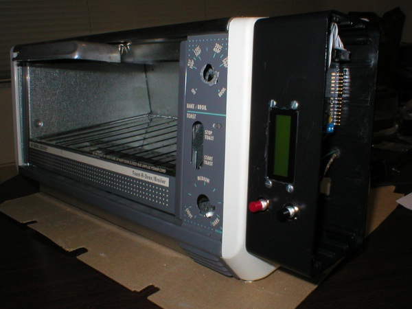
One of our awesome customer Scott, did some substantial amount of changes to the Reflow Controller Shield hardware and firmware wise. Instead of using a full blown Arduino main board, Scott used one of the Mini Ultra 8 MHz PCB that we gave away (sorry guys, not everyone managed to get them as we ran out stock towards the end) as the main controller. However, the Mini Ultra 8MHz requires an external FTDI cable or breakout board to upload the sketches from the Arduino IDE. Instead of using a FTDI cable, he uses a Silabs CP-2102 USB-to-Serial converter boards which can be purchased at USD3 from Ebay!

Scott also remove the 8×2 white on blue LCD included in the Reflow Controller Shield and replaced them with a bigger 16×2 LCD mounted on the panel. That is one of the reason we left the LCD removable instead of directly soldering them to the shield. The 2 on-board switches are also removed and an external push button is mounted on the panel. We’ll be adding extra solder pads for the tact switches and LED in the next revision of the shield to allow user to easily add external push buttons and LED.

From the firmware side, tonnes of improvements are made:
- Reduced 2 decimal points for temperature to 1 decimal point as integer degrees would be sufficient and provides more room for display.
- Display of the temperature slope so the rate of heating/cooling can be monitored (the difference between prior and current readings, which is also transmitted on the serial. This makes it easy to determine if one’s oven is performing within the 1 to 3 °C heating range and 1 to 6 °C cooling range specified in the JEDEC standard.
- Displaying a “remaining time” once the “soak stage” is started. Upon expiration of the timer, a 250ms buzzer beep is emitted and the “Reflow Stage” is entered. At that point, a “wet time” (the temperature above which the solder should be melting) is displayed but it does not start to count till the temperature hits 180 °C (per the JEDEC spec but is also user-settable). Once the peak (less 5 °C) is hit, the “Cool Stage” is entered and a 2 second alarm is emitted (“Open the door!”) but the “wet timer” continues to count until the temperature drops below 180 °C. The timer remains displayed until the “cool” threshold is reached.
The changes made to the firmware gives a lot attention to the reflow curve regulation which is very important if you plan to reflow quite often. Please notice that that the reflow profile is for leaded and non-RoHS use. Scott is happy enough to share the firmware and the schematic with everyone. See the attachment at the end of the post.

Scott uses a 4-heater element toaster oven from Black & Decker (it always works!) for his setup. Feel free try out the firmware and don’t forget to adjust the PID parameters to suit your setup!
Happy tinkering and take care.
Downloads:


Leave a Reply
Want to join the discussion?Feel free to contribute!