Forum Replies Created
-
AuthorPosts
-
LIM PHANG MOH
KeymasterOn SAMD21, only standby mode (lowest current) is supported.
KeymasterHi George,
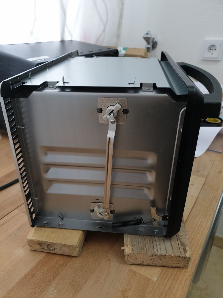
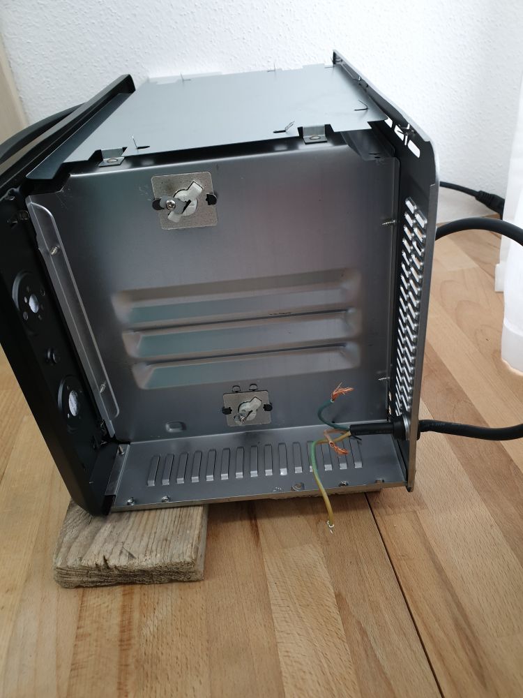
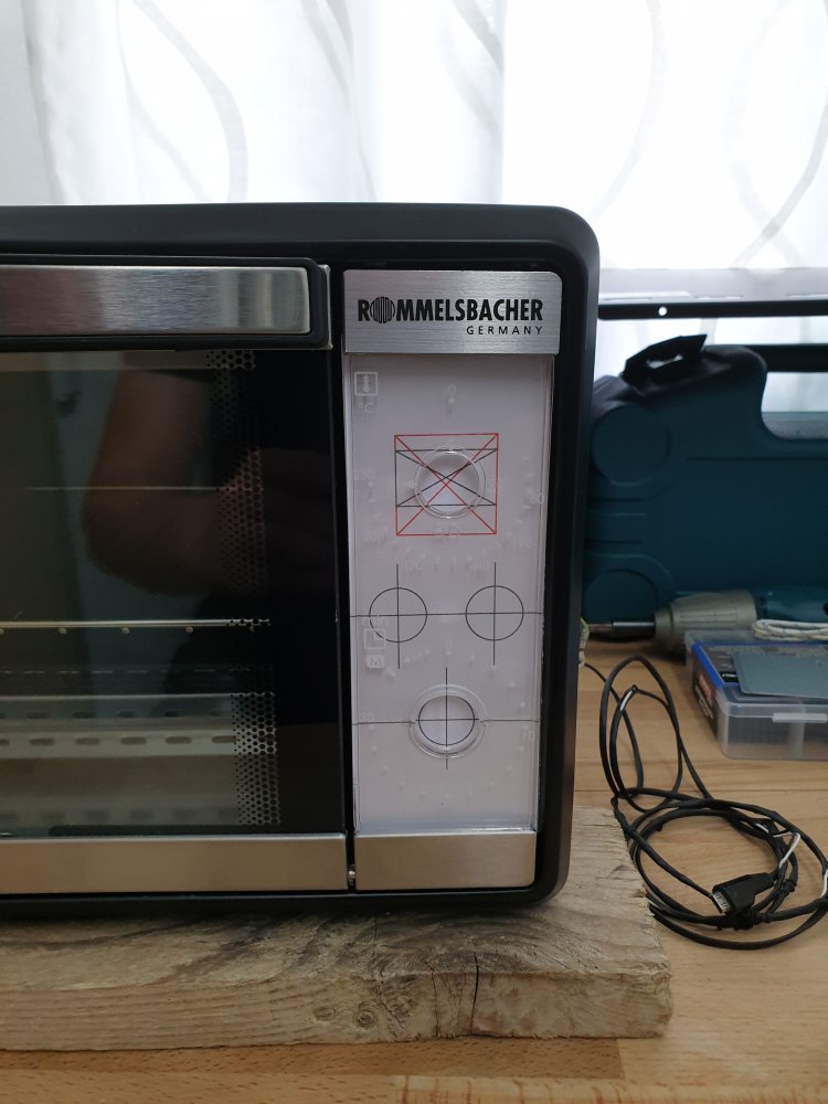
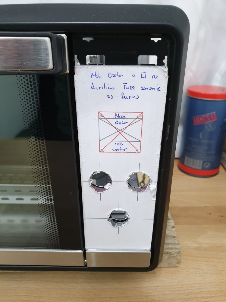
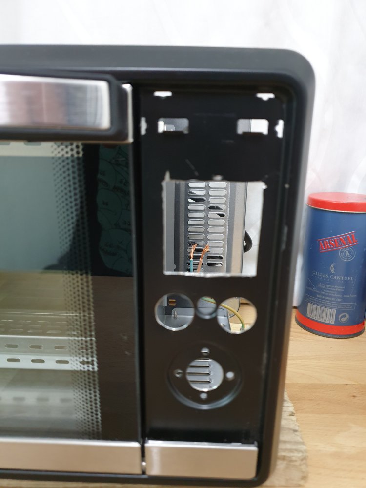
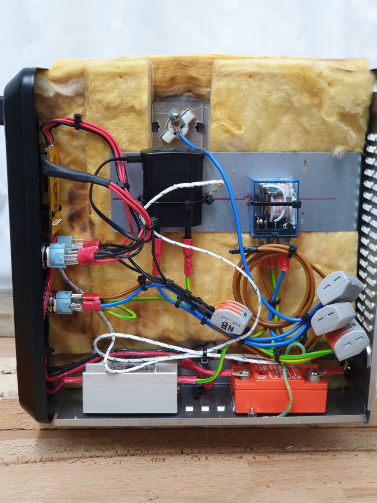
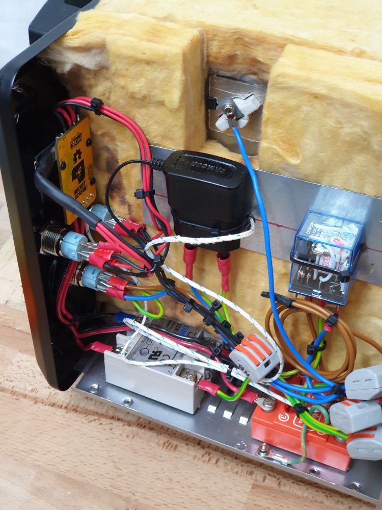
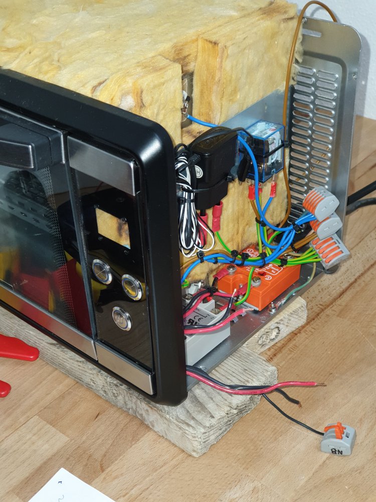
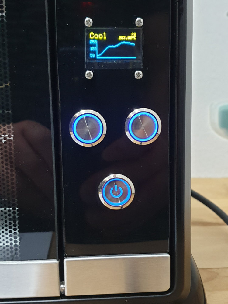
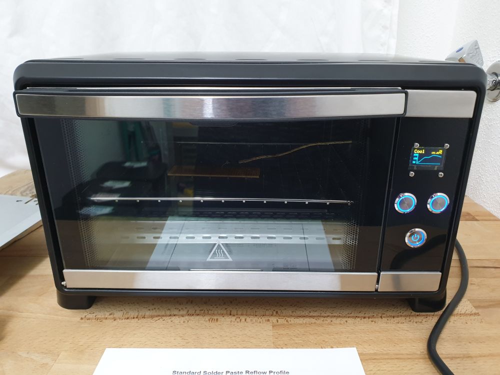
I haven’t personally try the latest version on the MCCI repository unfortunately. I will try this on a V3 board after Chinese New Year as I’m trying to finish some assembly date line.KeymasterReflow Oven Build by Antonio.
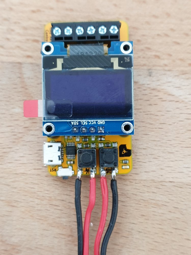
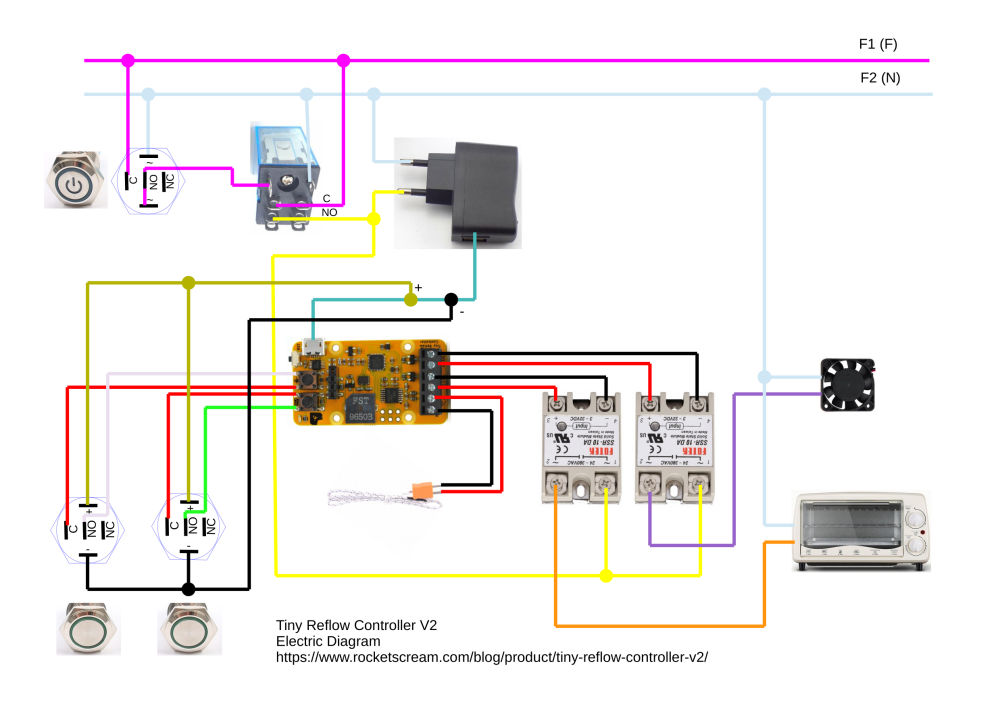
Uses the Tiny Reflow Controller V2.

 Keymaster
If you look at the datasheet in the sleep mode section, during power down only level interrupt works for INT0 and INT1. So, if you change the FALLING to LOW, it should work. I did a simple experiment here:
// **** INCLUDES ***** #include "LowPower.h" #define PIN_WAKEUP_A 2 #define PIN_WAKEUP_B 3 volatile boolean wakeUpA = false; volatile boolean wakeUpB = false; void setup() { pinMode(LED_BUILTIN, OUTPUT); pinMode(PIN_WAKEUP_A, INPUT_PULLUP); pinMode(PIN_WAKEUP_B, INPUT_PULLUP); digitalWrite(LED_BUILTIN, LOW); Serial.begin(115200); Serial.println("Start"); Serial.flush(); attachInterrupt(digitalPinToInterrupt(PIN_WAKEUP_A), triggerA, LOW); attachInterrupt(digitalPinToInterrupt(PIN_WAKEUP_B), triggerB, LOW); } void loop() { if (wakeUpA) { detachInterrupt(digitalPinToInterrupt(PIN_WAKEUP_A)); wakeUpA = false; Serial.println("A"); Serial.flush(); // LED should ON for 8s digitalWrite(LED_BUILTIN, HIGH); LowPower.powerDown(SLEEP_8S, ADC_OFF, BOD_OFF); digitalWrite(LED_BUILTIN, LOW); attachInterrupt(digitalPinToInterrupt(PIN_WAKEUP_A), triggerA, LOW); } if (wakeUpB) { detachInterrupt(digitalPinToInterrupt(PIN_WAKEUP_B)); wakeUpB = false; Serial.println("B"); Serial.flush(); // LED should ON for 2s digitalWrite(LED_BUILTIN, HIGH); LowPower.powerDown(SLEEP_2S, ADC_OFF, BOD_OFF); digitalWrite(LED_BUILTIN, LOW); attachInterrupt(digitalPinToInterrupt(PIN_WAKEUP_B), triggerB, LOW); } } void triggerA() { wakeUpA = true; } void triggerB() { wakeUpB = true; }KeymasterYour checking of the interrupt happens in between the enabling and disabling the interrupt regardless whether both of the sleep takes place. That doesn’t make sense. That is only us of time.
KeymasterHi,
Your code has only a fraction of time for the interrupt to happen as you enable the interrupt, check interrupt flag (which won’t happen), and detach interrupt. That won’t work.KeymasterIt’s most probably one of the pins are floating or contradicting with the state you have set them up with. Use a meter and check the pins for floating voltages.
And what sensor are you using? In most of the cases, the sensors are not low power enough.
KeymasterYou can test at these 2 points:
Just make sure you have a wet sponge to clean and wet the solder tip. Your solder joints looks like it’s not properly heated and murky in color. A bit of practice will help.
KeymasterHi Brian,
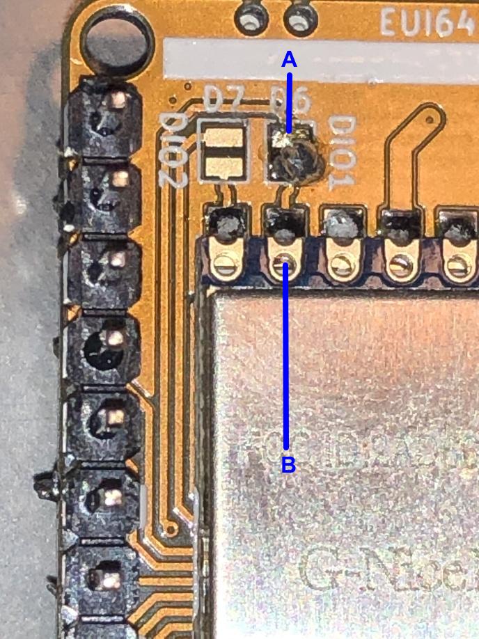
The one on the D6-DIO1 looks not properly soldered. They looks like cold solder joints for both (RESET too). May I know what temperature are you soldering at and what solder wire type is that?KeymasterCode on the node itself.
At least with the gateway logs, we could see if there’s any downlinks during the joining portion. That will allows us to see at what channels those downlinks were sent and if there’s any (which would again allow us to know if the join request were sent by the node).KeymasterDid you make any modification to the code? If yes, please post it here.
If you have access to the gateway, there will be logs for even raw LoRa packet. From there we can check whether at all the joining packets was received.
KeymasterD3-RESET and D6-DIO1
The RAK833 should work but make sure the channels enabled are the one of your interest.
All radios are tested and verified but using RadioHead library during testing. They should work.
Can I take a look at your solder joints?
KeymasterD3-RESET and D6-DIO1
The RAK833 should work but make sure the channels enabled are the one of your interest.
All radios are tested and verified but using RadioHead library during testing. They should work.
Can I take a look at your solder joints?
KeymasterIs the reset solder jumper closed too?
I put my APPEUI in REVERSED from what is shown in the TTN console.
Just make sure prior to that, you didn’t click the toggle LSB<->MSB button on TTN. The last 3 bytes in the code should be 0xD5, 0xB3, 0x70.
May I know if you are using a proper 8-channel gateway? And if yes, are the channels enabled correctly?
KeymasterHi Brian,
Most of these error are configuration errors like your keys wrongly entered on the code or TTN dashboard, the DIOx solder jumper not being closed/soldered, and using single channel gateway just to name a few.
Have you gone through the tutorial? -
AuthorPosts


