-
AuthorPosts
-
December 15, 2019 at 4:28 PM #14275
bpmcgee
ParticipantHi,
I’m using your example (https://github.com/rocketscream/MiniUltraPro/blob/master/ttn-otaa-sleep.ino) to test the radio. I’ve set up the keys, and set the config.h to read as follows:
//#define CFG_eu868 1
#define CFG_us915 1
// This is the SX1272/SX1273 radio, which is also used on the HopeRF
// RFM92 boards.
//#define CFG_sx1272_radio 1
// This is the SX1276/SX1277/SX1278/SX1279 radio, which is also used on
// the HopeRF RFM95 boards.
#define CFG_sx1276_radio 1
If I enable failure logging, I get the following result:
Starting
DEVEUI: 0x00 0x4 0xA3 0x0B 0x00 0xE8 0x6A 0xCC
Battery: 4.28 V
Packet queued
631693: EV_JOINING
FAILURE
C:\Users\bpmcg_000\Documents\Arduino\libraries\IBM_LMIC_framework\src\lmic\radio.c:660How do I go about troubleshooting this further?
Brian
December 15, 2019 at 4:58 PM #14279LIM PHANG MOH
KeymasterHi Brian,
Most of these error are configuration errors like your keys wrongly entered on the code or TTN dashboard, the DIOx solder jumper not being closed/soldered, and using single channel gateway just to name a few.
Have you gone through the tutorial?December 15, 2019 at 10:36 PM #14284ParticipantLim,
I did, thank you. That failure is an ASSERT in lmic\radio.c:
static void startrx (u1_t rxmode) {
    ASSERT( (readReg(RegOpMode) & OPMODE_MASK) == OPMODE_SLEEP );
    if(getSf(LMIC.rps) == FSK) { // FSK modem
        rxfsk(rxmode);
    } else { // LoRa modem
        rxlora(rxmode);
    }
    // the radio will go back to STANDBY mode as soon as the RX is finished
    // or timed out, and the corresponding IRQ will inform us about completion.
}
I’m not an expert, but it seems to be saying the library expected the radio to NOT be asleep but it was.
I soldered the connections on the underside of the board — DI01 and D3, although I’m a ham-fisted half-witted solderer. Is there a way for me to tell if the radio is up and operating?
I put my APPEUI in REVERSED from what is shown in the TTN console.
I put my DEVEUI into the TTN console AS SHOWN in the sketch output.
I put my APPKEY in AS SHOWN in the TTN console.I reset the board by unplugging it, and the sketch proceeds without the FAILURE assertion, but I still don’t get any events past “EV_JOINING”:
Starting
DEVEUI: 0x00 0x04 0xA3 0x0B 0x00 0xE8 0x6A 0xCC
Battery: 4.29 V
Packet queued
50167: EV_JOININGDecember 17, 2019 at 1:39 PM #14297KeymasterIs the reset solder jumper closed too?
I put my APPEUI in REVERSED from what is shown in the TTN console.
Just make sure prior to that, you didn’t click the toggle LSB<->MSB button on TTN. The last 3 bytes in the code should be 0xD5, 0xB3, 0x70.
May I know if you are using a proper 8-channel gateway? And if yes, are the channels enabled correctly?
December 17, 2019 at 2:18 PM #14299ParticipantD3 is reset, correct? I soldered DI01 and D3.
In the code, the last 3 bytes are as above.
The gateway I’m using is this https://uk.pi-supply.com/products/iot-lora-gateway-hat-for-raspberry-pi?_pos=39&_sid=2299b155b&_ss=r . It’s based on the RAK833 Gateway Concentrator Module, which I believe is multi-channel. I’m inquiring with the writer of the software if they’re in some way restricting it to a single channel.
How can I tell if the radio is on and working correctly?
B
December 17, 2019 at 2:25 PM #14301KeymasterD3-RESET and D6-DIO1
The RAK833 should work but make sure the channels enabled are the one of your interest.
All radios are tested and verified but using RadioHead library during testing. They should work.
Can I take a look at your solder joints?
December 17, 2019 at 2:27 PM #14303KeymasterD3-RESET and D6-DIO1
The RAK833 should work but make sure the channels enabled are the one of your interest.
All radios are tested and verified but using RadioHead library during testing. They should work.
Can I take a look at your solder joints?
December 17, 2019 at 2:36 PM #14305ParticipantI will take a picture next time I’m near it.
I am certain the radio worked when it left your shop. I’m worried that I may have either smoked it or I have a bad solder joint. Is there a way for me to test it to see if it’s working?
It’s an 8 channel gateway. I know with my Laird node I had to put it in subband 2 for it to work. I don’t currently have the source to the gateway program, so I can’t tell you right now which particular channels are enabled.
B
December 18, 2019 at 12:58 PM #14316KeymasterDid you make any modification to the code? If yes, please post it here.
If you have access to the gateway, there will be logs for even raw LoRa packet. From there we can check whether at all the joining packets was received.
December 19, 2019 at 10:04 AM #14329ParticipantSorry, to which code? The gateway? No. To your example? Just to replace the rtc alarm with a delay so that the USB doesn’t disconnect.
B
December 19, 2019 at 10:53 AM #14331KeymasterCode on the node itself.
At least with the gateway logs, we could see if there’s any downlinks during the joining portion. That will allows us to see at what channels those downlinks were sent and if there’s any (which would again allow us to know if the join request were sent by the node).December 22, 2019 at 3:11 AM #14356ParticipantSent to your gmail account.
December 22, 2019 at 12:51 PM #14364KeymasterHi Brian,
The one on the D6-DIO1 looks not properly soldered. They looks like cold solder joints for both (RESET too). May I know what temperature are you soldering at and what solder wire type is that?December 22, 2019 at 1:46 PM #14366ParticipantMy iron doesn’t have a temperature indicator. I had it set at 4.5 out of 5. The solder is 1.6mm lead-free rosin core solder.
I didn’t expect to have to do this fine level of soldering for this project, honestly. Even with a magnifying glass, my eyes are poor enough that I have a hard time seeing the joints. I can try again but I’m frightened of overheating the surface mount joints near them — particularly D6-DI01.
Are there test points that I can use with my multimeter to tell if the joints are good?
December 22, 2019 at 1:55 PM #14369KeymasterYou can test at these 2 points:
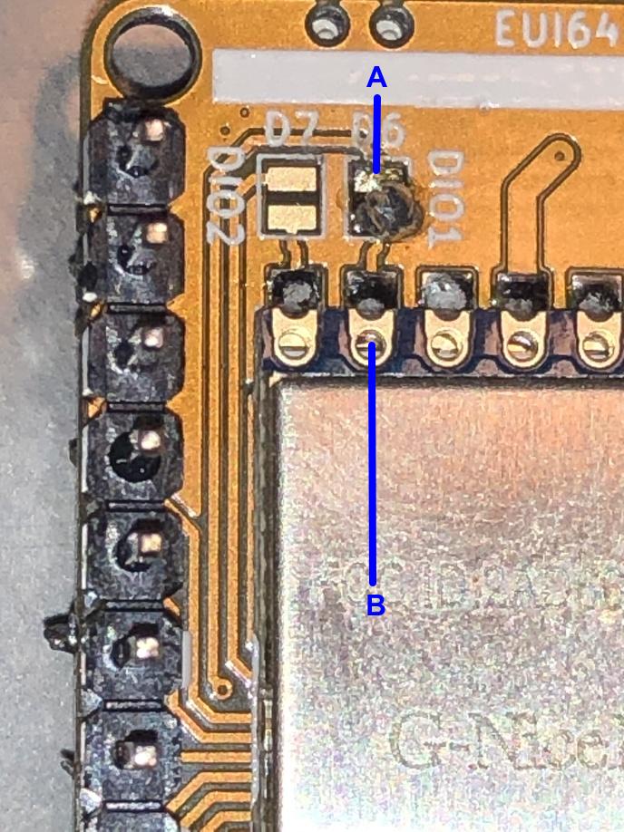
Just make sure you have a wet sponge to clean and wet the solder tip. Your solder joints looks like it’s not properly heated and murky in color. A bit of practice will help.
-
AuthorPosts
- You must be logged in to reply to this topic.


