New Product – Tiny Reflow Controller
Our Reflow Oven Controller Shield has been around for many years now. It went through minor changes over the years and we were fortunate to ship out a lot of them. But, we always felt that we are not doing enough in pushing the overall cost further down to provide a lower entry to get into SMD reflowing. The need for an external Arduino board as the brain for the setup adds a massive cost to the shield (depending on whether you buy an official board from Arduino or a copy online). The new Tiny Reflow Controller is a derivative design from the shield version to address those tiny little issues.
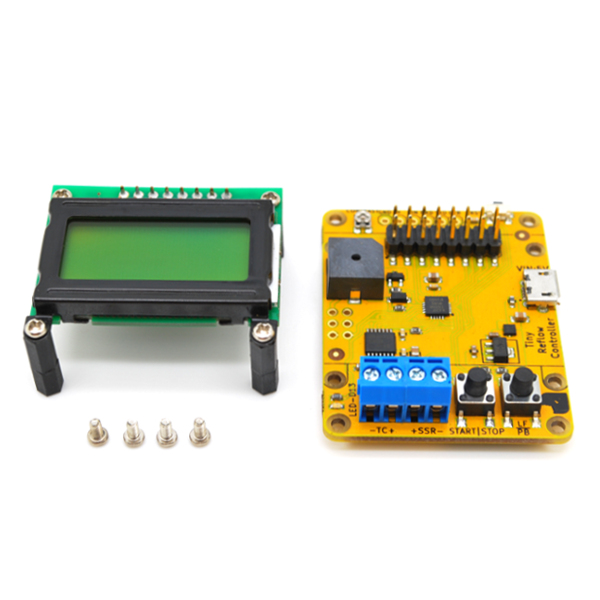
The new Tiny Reflow Controller is powered by the ATtiny1634R coupled with the latest thermocouple sensor interface IC MAX31856 from Maxim, we managed to remove the need of an Arduino board and reduce the overall cost. We also use as much SMD parts in this revision to keep the cost low and leaving only the terminal block and the LCD connector on through hole version. We also managed to streamline all components to run on 3.3V to further simplify the design.
Looking from the manufacturing point of view, there’s quite a number of through hole components that adds much of the work of manual soldering and cleaning the solder residue in the shield version. And each unit is individually tested to reflow a complete cycle and compare with measurement from a thermocouple reading from a multimeter. That takes a massive 10 minutes of time to perform. For some of you that has used the shield version before must have came across the wrongly calibrated MAX31855KASA by Maxim (those affected were contacted for exchange circa 2014), that is one of the reason it was tested in that manner. But, this is one of the manufacturing step that we still insist on performing on the new Tiny Reflow Controller.
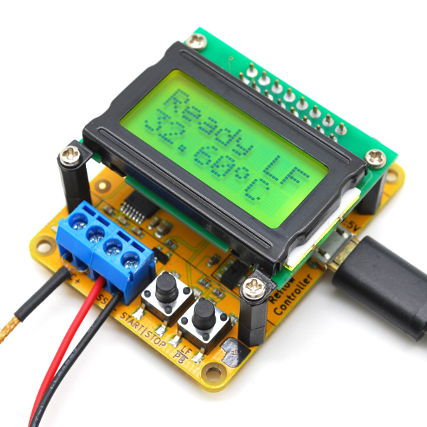
We maintained the 8×2 LCD used in the shield due to it’s robustness but a 3.3V version is used to simplify the design (we know some of you are screaming for the OLED screen). The board is now powered through a micro USB connector as most of us have a spare micro USB cable lying somewhere. You can also power the board through the FTDI breakout header on the board. You can use a 3.3V FTDI USB-serial adapter (or any similar USB-serial adapter) to access the UART on the ATtiny1634R and also perform update through the Arduino IDE. The ISP pins are also broken out in case if you need to modify the bootloader or program the ATtiny1634R directly without a bootloader.
On the firmware side, we added the option of selecting either lead-free or leaded profile. The profile can be selected through the push button and currently selected profile is stored on the non-volatile EEPROM on the ATtiny1634R. Despite having 16 kB of program memory flash and 1 kB of RAM only, the current firmware only uses 10 kB of the 16 kB program memory flash and half of the 1 kB RAM leaving lots of room for tinkering. We would like to thank Spence Konde for his amazing work on the ATTinyCore.
And as always, the Tiny Reflow Controller is an open source hardware and is even better as it is designed with KiCad. We hope you will find the Tiny Reflow Controller helpful and big in it’s own way!


Leave a Reply
Want to join the discussion?Feel free to contribute!