The SX1276 Modules Shootout – HopeRF’s RFM95W vs NiceRF’s LORA1276-C1 vs HPDTEK’s HPD13
Few months back, a customer of ours asked whether we could get a shielded version of the HopeRF’s RFM95W on our Mini Ultra Pro boards. And sure we asked HopeRF whether they are willing to provide a custom version with a metal shield. They gave us a quotation and a minimum order quantity (MOQ) to fulfilled. Unfortunately, the MOQ were too high for either of us. So, we went on to search high and low for a LoRa SX1276 based module with a shield. At first we stumbled upon NiceRF’s LORA1276-100mW but it doesn’t have the same form factor as the RFM95W. But, we went on and made a prototype board with it. On paper it looks great but as soon as we assembled the very first few units using our reflow oven, we notice that one side of the module would be slightly lifted due to the imbalance of the module pinout (it has 12 pads on 1 side and another 2 pads on the opposite side corner of the module). The solder tension on the side with 12 pads are stronger compare to the other side of the module. We believe that this will somehow create some potential issues in manufacturing. So, we dropped the plan.
Disappointing find but we didn’t throw the towel just yet, we went and asked NiceRF whether they have plans to make a shielded version that has similar footprint as the RFM95W in the near future. Unfortunately they replied with a not so convincing answer stating that “maybe they would”. But, about 2 months ago, NiceRF gave a big surprise by releasing the LORA1276-C1 module that has the same form factor and pinout as the HopeRF’s RFM95W, except that it comes with a shield! Having the exact form factor and pinout would be great as we can swap them in on our Mini Ultra Pro board if anyone needs a shielded version. We went on and ordered a few pieces to try them out.
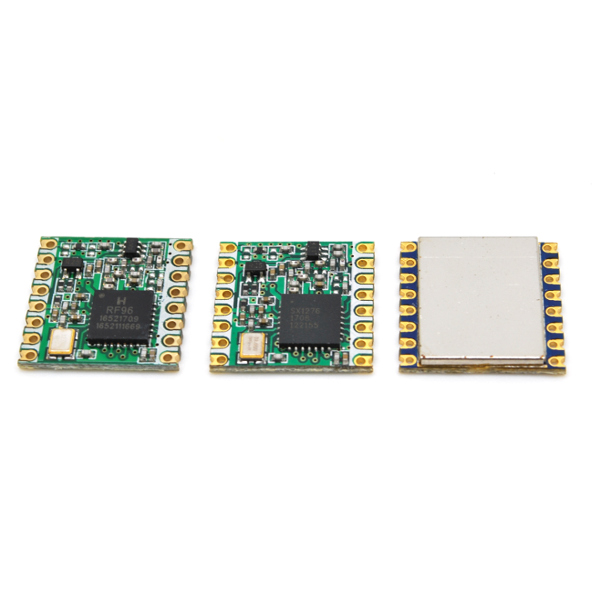
By luck, we also stumbled upon HPDTEK’s HPD13 module that has the exact some form factor, pinout and even PCB layout of HopeRF’s RFM95W. We believe they are exact copies of the RFM95W although HopeRF’s SX1276 chip has their own marking of “RF96” with the “H logo” while HPDTEK uses the off-the-shelf SX1276 like NiceRF. Here’s how the 3 module looks like (RFM95W, HPD13, LORA1276-C1) side by side.
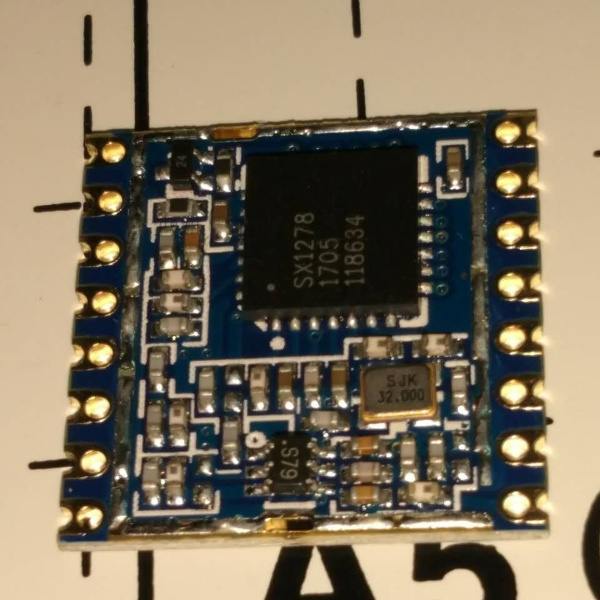
We have yet to desolder the metal shield off the NiceRF’s LORA1276-C1 module but they have provided an image of their LORA1278-C1 (SX1278 based for 433MHz band) module without the metal shield. Here’s how it looks like and as you can see the PCB layout is totally different from the HopeRF’s RFM95W.
We are curious how these modules perform especially in the range test. We believe crucial factors like PCB layout, component values tolerance and PCB material (just to name a few) will affects how they perform. We wanted to perform a range test that would be able to provide some statistical data and most importantly run in the condition close to a real world deployment.
Setup
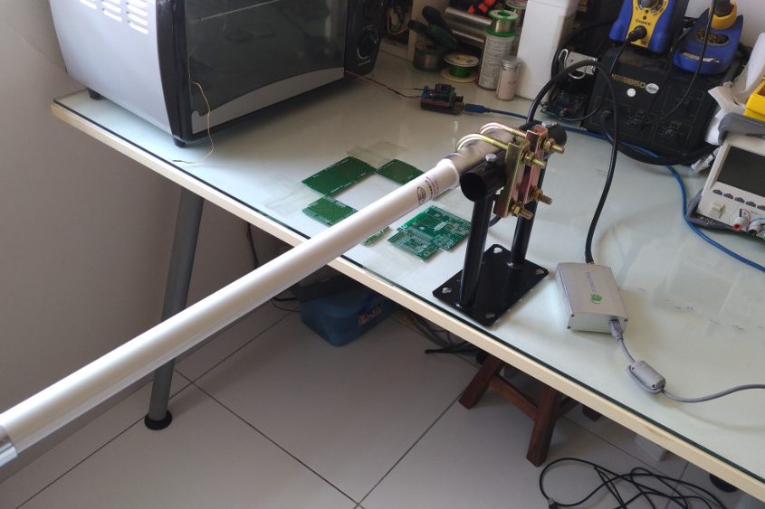
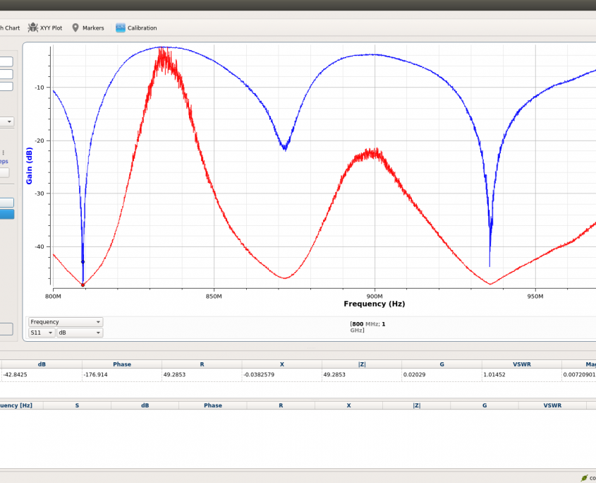
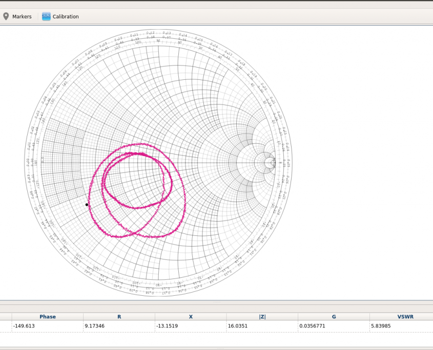
Our plan was to perform a range test using a pair of Mini Ultra Pro assembled with the same type of module and compare them. Each pair will consist of a stagnant base station and mobile node. The base station unit is mounted on the roof top of a 2 storey high building. We recently bought a 58 cm long 5 dBi antenna that has a very good S11 and VSWR performance. We plan to use it on a TTN gateway. Here’s how it looks like in the lab while being measured it’s S11 and VSWR characteristic using a pocketVNA.
The resulting S11 and VSWR measurement were spot on especially on the 868 MHz band.
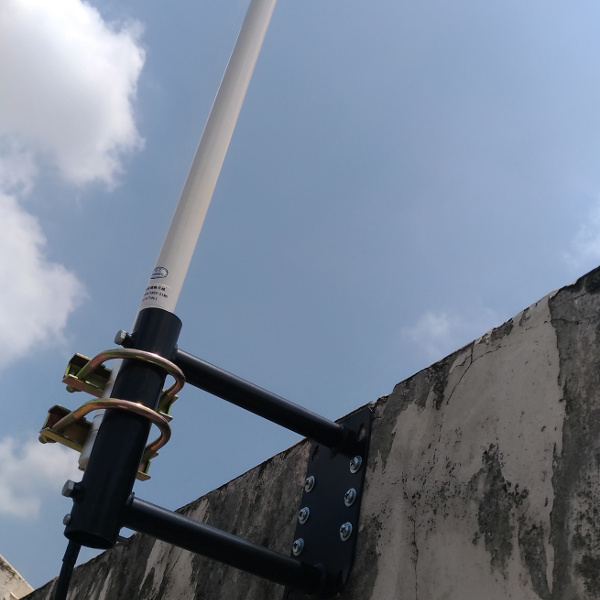
Armed with a driller and hammer, we assembled the antenna bracket mount on the highest possible wall on the rooftop.
Here’s how the antenna looks like once the assembly is completed.
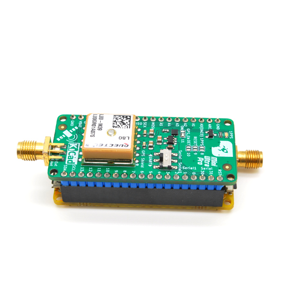
On the mobile node, the Mini Ultra Pro will be equipped with a GPS shield powered by Quectel’s L80 GPS module (we’ll be releasing this soon!) to keep track of the location where transmission and reception is successful. This location information (latitude, longitude and host of other information) is then log onto (using SerialFlash library) the Mini Ultra Pro on-board 2MB serial flash in CSV format which can be retrieved later for further analysis.The mobile node will periodically send a data package to the base station and expects an acknowledgement from the base station. If a valid acknowledgement packet is received, the current GPS information (using TinyGPS library) is retrieved from L80 GPS module and stored. Some of you might have argue why not use the full LoRaWAN stack (using Arduino-LMIC library) and run it using the The Things Network backend? As LoRaWAN network such as the TTN has duty cycle limitation and maximum airtime that can be used in a day (30 s), it does not go well with our test that requires frequent data transmission.
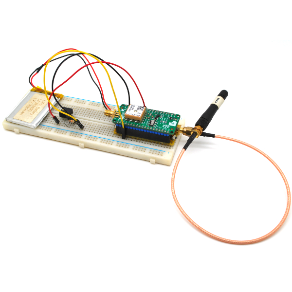
Both the base station and the mobile node are powered by Li-Polymer batteries. The mobile node is also attached to an external buzzer circuitry to indicate when a data packet is successfully transmitted and GPS information is logged onto the on-board serial flash. We use our 3 dBi 868 MHz antenna through a RP-SMA jack to SMA adapter cable. The mobile node setup is placed at the back of a car’s windscreen with the antenna position vertically.
Code
On the firmware side, the base station has a rather simple structure that acknowledges a data packet send by the mobile node. The RadioHead library handles the acknowledgement process of a data packet automatically. Here’s how the base station code looks like (code are mostly derived from the examples on RadioHead library). Do note that we used a custom setting on the radio of Bw125Cr45Sf4096 to mimic one of the physical layer settings (SF=12, BW=125 kHz, CR=4/5) used in LoRaWAN network which can be added in the RH_RF95.h and RH_RF95.cpp files of the RadioHead library.
#include <RHReliableDatagram.h>
#include <RH_RF95.h>
#include <SPI.h>

#define NODE_ADDRESS 1
#define BASE_STATION_ADDRESS 2

// Singleton instance of the radio driver
RH_RF95 driver(5, 2);

// Class to manage message delivery and receipt, using the driver declared above
RHReliableDatagram radio(driver, BASE_STATION_ADDRESS);

void setup()
{
  // Initialize LED pin
  pinMode(13, OUTPUT);
  digitalWrite(13, LOW);
  // Initialize serial flash CS pin
  pinMode(4, OUTPUT);
  digitalWrite(4, HIGH);

  // Enable debugging serial port
  SerialUSB.begin(115200);

  // Initialize radio
  if (!radio.init()) SerialUSB.println("init failed");
  // Maximum transmit power at 23 dBm
  driver.setTxPower(23, false);
  // 868 MHz frequency
  driver.setFrequency(868.00);
  // CR=4/5, SF=12, BW=125 kHz
  driver.setModemConfig(RH_RF95::Bw125Cr45Sf4096);
}

void loop()
{
  unsigned char buf[RH_RF95_MAX_MESSAGE_LEN];

  if (radio.available())
  {
    // Wait for a message addressed to us from the client
    uint8_t len = sizeof(buf);
    uint8_t from;
    if (radio.recvfromAck(buf, &len, &from))
    {

    }
  }
}
The mobile node sends a 1 byte (see below for the explanation) and expects an acknowledgement packet from the base station. And in the case where it does receive a valid acknowledgement, it will retrieve the current GPS information and log them onto the on-board serial flash. To retrieve these logged information, simply connect the USB port to a serial terminal and send any character to the board. All the current logged GPS information will be retrieved and the serial flash will be erased after that. Here’s how the mobile node code looks like (the dtostrf function on SAMD21 are provided by jsmith as currently it is not implemented on the SAMD21 Arduino core):
#include <RHReliableDatagram.h>
#include <RH_RF95.h>
#include <TinyGPS.h>
#include <SerialFlash.h>
#include <SPI.h>
#include <stdlib.h>

#define NODE_ADDRESS 1
#define BASE_STATION_ADDRESS 2

// Singleton instance of the radio driver
RH_RF95 driver(5, 2);
// GPS driver
TinyGPS gps;
SerialFlashFile flashFile;

// Class to manage message delivery and receipt, using the driver declared above
RHReliableDatagram radio(driver, NODE_ADDRESS);

unsigned int counter;

void setup()
{
  // Initialize LED pin
  pinMode(13, OUTPUT);
  digitalWrite(13, LOW);
  // Initialize serial flash CS pin
  pinMode(4, OUTPUT);
  digitalWrite(4, HIGH);
  // Initialize serial flash CS pin
  pinMode(5, OUTPUT);
  digitalWrite(5, HIGH);

  // Enable GPS serial port
  Serial.begin(9600);
  // Enable debugging serial port
  SerialUSB.begin(115200);
  //while (!SerialUSB) {};

  SerialFlash.begin(4);

  if (!SerialFlash.exists("SX1276.CSV"))
  {
    SerialUSB.println("SX1276.CSV does not exist");
    if (SerialFlash.create("SX1276.CSV", 1000000))
    {
      SerialUSB.println("SX1276.CSV is created");
    }
    else
    {
      SerialUSB.println("Unable to create file");
    }
  }
  else
  {
    SerialUSB.println("SX1276.CSV is already created");
  }

  flashFile = SerialFlash.open("SX1276.CSV");
  if (!flashFile)
  {
    while (1)
    {
      digitalWrite(13, HIGH);
      delay(100);
      digitalWrite(13, LOW);
      delay(100);
    }
  }
  else
  {
    SerialUSB.println("SX1276.CSV is open");
  }

  // Initialize radio
  if (!radio.init()) SerialUSB.println("Radio failed");

  // Maximum transmit power at 23 dBm
  driver.setTxPower(23, false);
  // 868 MHz frequency
  driver.setFrequency(868.00);
  // CR=4/5, SF=12, BW=125 kHz
  driver.setModemConfig(RH_RF95::Bw125Cr45Sf4096);
  radio.setTimeout(1000);
  SerialUSB.println("Counter,Latitude,Longitude,Satellite,HDOP,SNR");
}

void loop()
{
  char gpsData[12];
  char logData[50];
  char *logDataPtr;
  unsigned char data[] = "1";
  unsigned long readCounter;
  int snr;
  bool newData = false;

  // Send a message to base station
  if (radio.sendtoWait(data, sizeof(data), BASE_STATION_ADDRESS))
  {
    snr = driver.lastSNR();
    digitalWrite(13, HIGH);
    counter++;
    // Parse GPS data for 1 s
    for (unsigned long start = millis(); millis() - start < 1000;)
    {
      while (Serial.available())
      {
        char c = Serial.read();
        // SerialUSB.write(c);
        if (gps.encode(c))
        newData = true;
      }
    }
    if (newData)
    {
      float flat, flon;
      unsigned long age;
      gps.f_get_position(&flat, &flon, &age);

      sprintf (gpsData, "%u", counter);
      strcpy(logData, gpsData);
      strcat(logData, ",");
      dtostrf(flat, 3, 6, gpsData);
      strcat(logData, gpsData);
      strcat(logData, ",");
      dtostrf(flon, 3, 6, gpsData);
      strcat(logData, gpsData);
      strcat(logData, ",");
      sprintf (gpsData, "%u", gps.satellites());
      strcat(logData, gpsData);
      strcat(logData, ",");
      sprintf (gpsData, "%u", gps.hdop());
      strcat(logData, gpsData);
      strcat(logData, ",");
      sprintf (gpsData, "%d", snr);
      strcat(logData, gpsData);
      strcat(logData, "\r\n");
      // Terminate the log data
      strcat(logData, "\0");
      // Push location data to indicate successful transmission & reception at current location
      SerialUSB.print(logData);
      // Log location data onto serial flash
      flashFile.write(logData, strlen(logData));
    }

    digitalWrite(13, LOW);
  }
  else
  {
  //SerialUSB.println("TX failed");
  }
  if (SerialUSB.available())
  {
    while (SerialUSB.available()) SerialUSB.read();
    flashFile.close();
    flashFile = SerialFlash.open("SX1276.CSV");
    if (flashFile)
    {
      digitalWrite(13, HIGH);
      readCounter = flashFile.size();
      SerialUSB.println("File will be deleted after reading!");
      SerialUSB.println("Counter,Latitude,Longitude,Satellite,HDOP,SNR");

      while (readCounter > 0)
      {
        // Read 1 byte at a time
        flashFile.read(gpsData, 1);
        if ((gpsData[0] >= '0') && (gpsData[0] <= '9') ||
            (gpsData[0] == '.') || (gpsData[0] == ',') ||
            (gpsData[0] == '\r') || (gpsData[0] == '\n'))
        {
          readCounter -= 1;
          SerialUSB.print(gpsData);
        }
        // End of file
        else break;
      }
      digitalWrite(13, LOW);
    }
    else
    {
      SerialUSB.println("Unable to open file");
    }
    flashFile.close();
    SerialFlash.eraseAll();
    while (!SerialFlash.ready())
    {
      delay(500);
      digitalWrite(13, HIGH);
      delay(500);
      digitalWrite(13, LOW);
    }
    SerialFlash.create("SX1276.CSV", 1000000);
    flashFile = SerialFlash.open("SX1276.CSV");
  }
  // Provide gaps in between transmission
  delay(500);
}

// dtostrf function on SAMD21 are provided by jsmith:
// http://forum.arduino.cc/index.php?topic=368720.0
char *dtostrf(double value, int width, unsigned int precision, char *result)
{
  int decpt, sign, reqd, pad;
  const char *s, *e;
  char *p;
  s = fcvt(value, precision, &decpt, &sign);
  if (precision == 0 && decpt == 0) {
    s = (*s < '5') ? "0" : "1"; reqd = 1; } else { reqd = strlen(s); if (reqd > decpt) reqd++;
    if (decpt == 0) reqd++;
  }
  if (sign) reqd++;
  p = result;
  e = p + reqd;
  pad = width - reqd;
  if (pad > 0) {
    e += pad;
    while (pad-- > 0) *p++ = ' ';
  }
  if (sign) *p++ = '-';
  if (decpt <= 0 && precision > 0) {
    *p++ = '0';
    *p++ = '.';
    e++;
    while ( decpt < 0 ) {
      decpt++;
      *p++ = '0';
    }
  }
  while (p < e) {
    *p++ = *s++;
    if (p == e) break;
    if (--decpt == 0) *p++ = '.';
  }
  if (width < 0) { pad = (reqd + width) * -1; while (pad-- > 0) *p++ = ' ';
  }
  *p = 0;
  return result;
}
Outcome
After running the test for a different pairs of the modules, here’s how the range test plot turns out!
From the plot, all the modules performs fairly well within the 3 km range but beyond that it becomes patchy depending on the location and module. The furthest point achieve is around 6.4 km. Under any circumstances, there were no line of sight link between the base station and the mobile node. This scenario provides a better real world usage assessment of the LoRa module rather than using a clear line of sight test condition. Take a look at the plot for yourself and use the measurement tool to see far these module could go! 2 years ago, we could achieve up to 10 km of range but as the city grows with more tall buildings and denser vegetation these results in shorter range in the present.
Further Work
We have been working on the SX1276 based modules for more than 2 years now. We found out that with long range settings such as using Spreading Factor (SF) of 12 and 125 kHz of bandwidth does not work reliably with the crystal based modules. This is more apparent when long data is being sent over the channel. This is due to the tolerance of the crystal used on these modules rated at 10 ppm (advertised as such). Across wider temperature range, it will further deviate. This is the reason we used a single byte data in the test code (RadioHead library will add a few more bytes in the header of the data packet). We were lucky enough to get our hands on a TCXO based (replaces the less accurate crystal with a better 2 ppm tolerance) module (RFM95TW) made by HopeRF. Even though these TCXO based module solves the issues at high SF and small and bandwidth setting, they are not low power as it continues to run even though the radio transceiver chip is in sleep mode. This result in a huge 600 uA (vs 0.1 uA)of sleep current!
We have yet to measure to output power of these modules and we hope to do so in the near future (provided we have the correct tools). Mike McCauley (author of RadioHeadlibrary) did some output power measurement on the RFM95W but it would be great to be able to compare them.
Conclusion
We have yet to decide on whether to swap out the RFM95W module from our Mini Ultra Pro V2 with any of the other 2 modules. But, the having a shielded radio module is a very interesting point to ponder. We are not allowed to discuss the pricing point of view of these modules but they do vary from one and another. Do let us know what you guys think!


Hi,
Have you had a chance to compare the RF performance of those modules with any “branded” ones? I have a node based on NiceRF Lora1276 – functionally works flawlessly. When it comes to RF performance – I’m a bit confised.
The gateway is located in my room, kind of 5-6 meters away from the node. It reports the following RX params:
frequency:”868500000″
loRaSNR:-13.2
rssi:-108
Out of curiosity, I unplugged the Lora1276 module and replaced it with Semtech SX1276MB1MAS mbed shield, with exactly the same antenna. Surprisingly, the RX params were
frequency:”868300000″
loRaSNR:8
rssi:-88
So – the same node, the same software, the same location, the same antenna, completely different signal quality. In both cases SF=12, BW=125kHz
Both boards have complete different layout and probably different components too. Although the antenna port is matched and are said to be rated at 50 Ohm, when match with any antenna (again an unknown parameter) it could be produce different results. When I placed the base station unit on the roof top, the end node inside the room (about 5 meters apart), it stays around 7-9 dBm. Is the antenna used in your test case came with the mBed kit?
Tried different antennas, different combinations. The original mbed antenna too. The gateway RSSI and SNR readouts are the same (more or less): -13/-108 if Lora1276 is used, +8/-88 when using mbed shield.
The other thing is that it’s node -> gateway path which is giving me my concerns. The gateway -> node signal is OK, as fat as I understand the numbers. This is the best I could get for Lora1276 with an outdoor antennas
Lora1276 -> iC880, RSSI=-100, SNR=3
iC880 -> Lora1276, RSSI=-48, SNR=34
This is the asymetry which is worrying me the most. And that mbed shield does not have this issue. I’d really want to understand what I get and where the problem is before I get crazy and start designing my own RF path 🙂
OK, the problem is solved. NiceRF modules, in the contrary to Semtech mbed sield, uses the PA_BOOST output of SX1276, instead of RFO_HF. Setting the PACONFIG register bit 7 to “1” unconditionally configures the HF TX path correctly.
I totally miss that! Yes, all the cheaper modules out there usually uses the PA_BOOST output configuration. It was written somewhere in the RadioHead library as a reminder. Glad that it works. 🙂
Hi, just wondering where you purchased the antenna ( 58 cm long 5 dBi antenna) used? thanks 🙂
Hi Vince,
We bought it from Taobao. If you don’t have access to Taobao, there’s plenty on Aliexpress.