• Twitter
  • Youtube
Rocket Scream
  • Blog
  • Shop
    • Arduino and Compatibles
      • Mini Ultra Series
      • osPID
    • Component
      • Connector
      • Interconnect & Cables
      • Wires
      • Sensors
        • Temperature
    • Wireless
      • Antenna
      • Module
  • Forums
  • Docs
  • Contact
  • About
  • My Account
  • Search
  • Menu Menu
  • 0Shopping Cart

Getting Started With Red Comet ESP32

You are here: Home1 / Docs2 / Getting Started With Red Comet ESP32
Overview

Red Comet ESP32

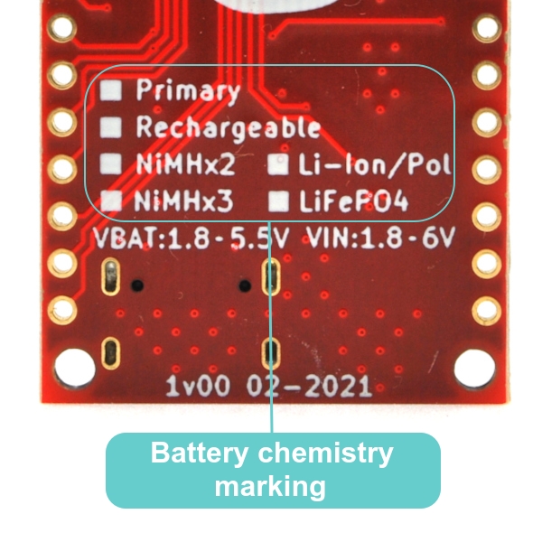
Our first hooray into the ESP32 world! We weren’t convinced with ESP32 (or it’s predecessor ESP8266) until a custom design client forced us to design an ultra low power wireless data logger based on the EPS32. We initially felt that the reset behavior upon waking up from deep sleep were weird and unconventional. But after diving deep while designing the custom board, that was when we thought what we have been missing all this while. There are tonnes of ESp32 boards out there and some are very well designed too. But, we never found one that is ultra low power and can be powered by various type of primary or rechargeable batteries. We believe that certain battery chemistry fit better in certain application and no single battery type could be best for everything.

Specifications:

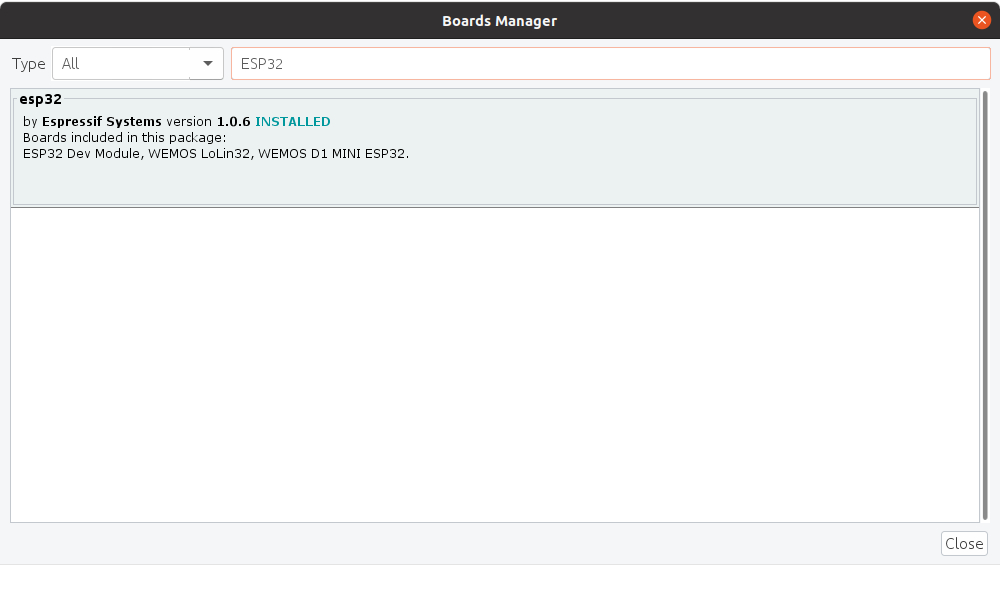
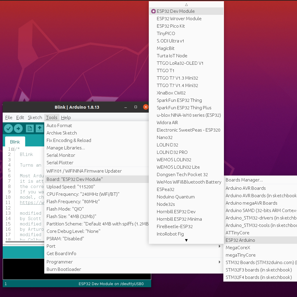
  • Compatible with Arduino IDE using ESP32Arduino core
  • Module:
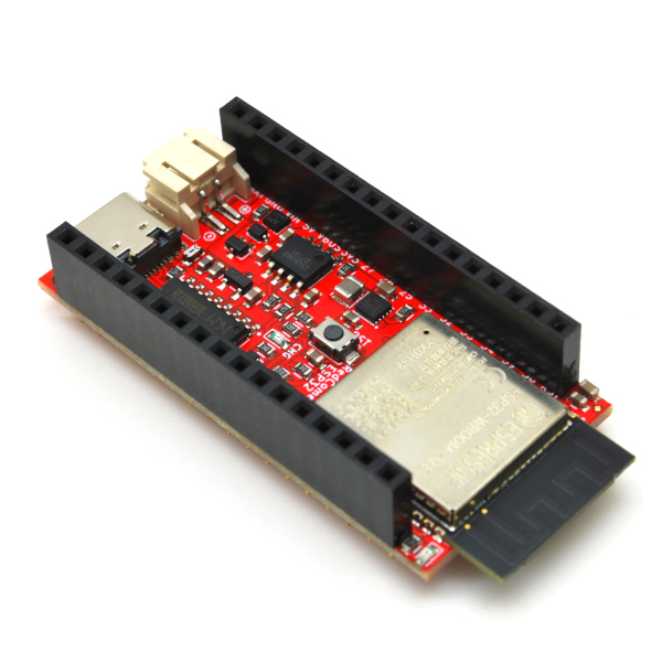
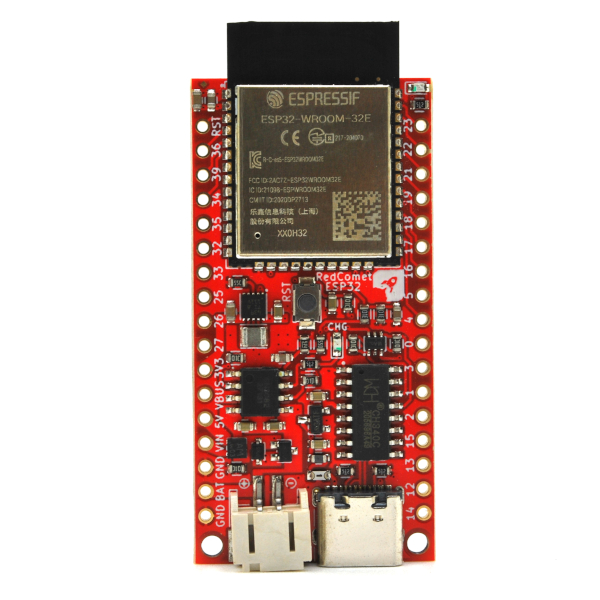
    • ESP32-WROOM-UE (IPEX connector) or ESP32-WROOM-E (integrated PCB antenna)
    • 4 MB SPI flash
    • ESP32-D0WD-V3 embedded, Xtensa® dual-core 32-bit LX6 microprocessor, up to 240 MHz
    • 448 KB ROM for booting and core functions
    • 520 KB SRAM for data and instructions
    • 16 KB SRAM in RTC
  • Operating voltage: 3.3 V
  • Low quiescent current (0.075 μA) on-board 3.3 V 400 mA buck-boost switching regulator
  • Ultra low power:
    • Rechargeable battery version: minimum 13.0 μA in sleep mode with input at 3.6V
    • Non-rechargeable battery version: minimum 10.0 μA in sleep mode with input at 3.6V
  • Power source:
    • Auto power switching between power source applied on the VBAT, VIN or USB
    • External DC source range: 1.8 – 6 V
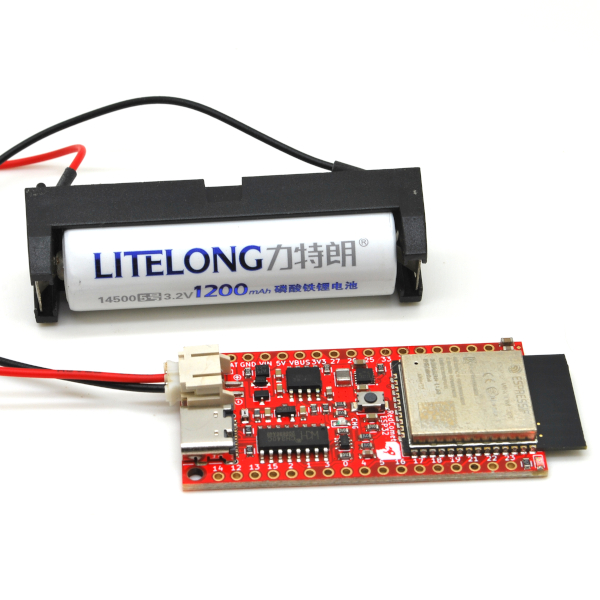
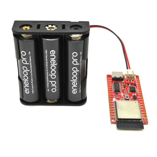
    • Option to use various battery type, cell combination and chemistry such:
      • Rechargeable: 3xAA NiMH, LiFeFO4, Li-Ion/Pol
      • Non-rechargeable: 3xAA or 4xAA (alkaline, lithium), 3V CR123A lithium, lithium-thionyl chloride (Li-SOCl2), lithium-manganese dioxide (Li-MnO2)
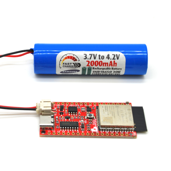
  • On-board battery charger:
    • CN3082 battery charger IC that supports multi-chemistry battery including Li-Ion/Pol, NiMH, & LiFeFO4
    • Input to charging circuitry is solar panel optimized akin to MPPT (charge current reduces when solar panel voltage reduces to prevent total collapse of input voltage)
    • 195 mA maximum charge current
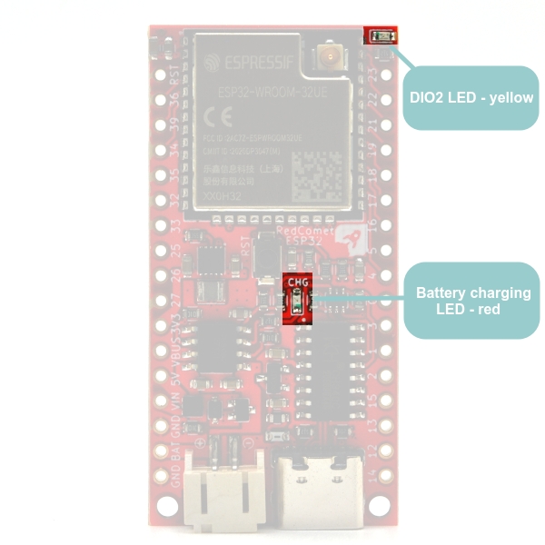
    • Yellow indicator LED for charging status
    • Battery charger circuitry not mounted for non-rechargeable battery version
  • Red indicator LED connected to pin IO2
  • USB-serial interface through CH340C with auto-reset to enter bootloading mode
  • USB type-C reversible connector for robust and long lasting usage
  • JST PH 2.0 mm battery connector
  • Battery power monitoring on pin IO35
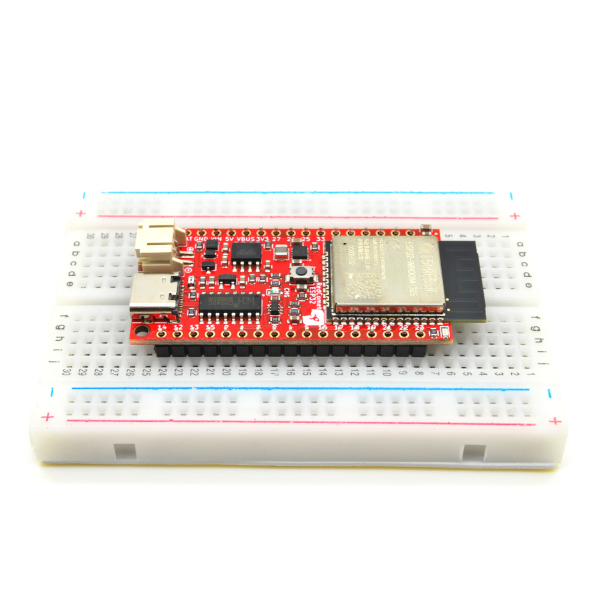
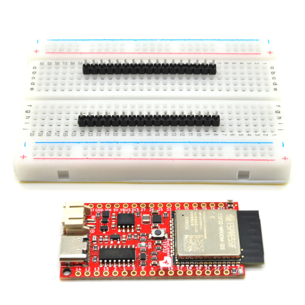
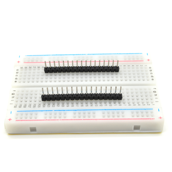
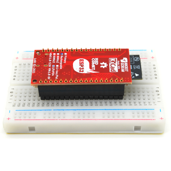
  • 900 mil in between 2 breakout headers – suitable for breadboard usage
  • Dimension:
    • IPEX connector: 25.4 mm x 50.8 mm (1.00″ x 2.00″)
    • Integrated PCB antenna: 25.4 mm x 56.54 mm (1.00″ x 2.23″)
  • FR-4 1.6 mm 4-layer PCB with ENIG surface finish
  • RoHS compliant: Yes!
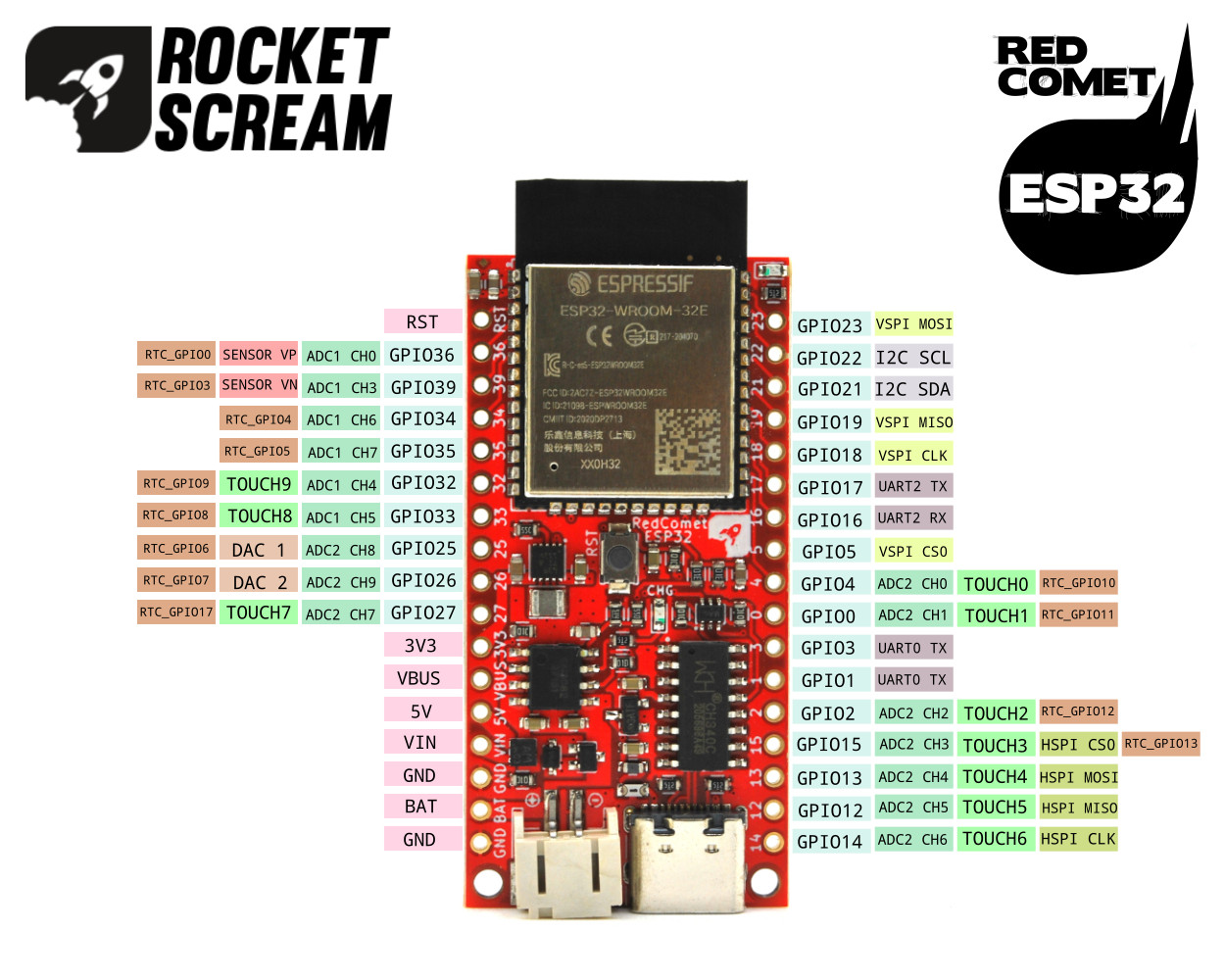
Pinout

Red Comet ESP32Power Pins
The power pins available on the Red Comet ESP32 are as follows:

  • GND – The common GND for the board.
  • BAT – Battery input positive supply. Battery power is supplied through the JST PH 2.0 mm connector or the BAT pin on the breakout pad.
  • VIN – External voltage input positive supply. An input voltage range of (1.8-6 V) is allowed. In order to charge the respective batteries used on the board, the VIN must be higher than the VBAT by 0.4 V.
  • 5V – USB 5 V supply if the USB Type-C is connected.
  • VBUS – The positive voltage output from the onboard power management circuitry that can be either VBAT, VIN or 5V USB.  All subsequent voltage rails (if required) should be derived from this VBUS supply. 
  • 3V3 – Output from the onboard 3.3V buck-boost regulator. A maximum of 400 mA of current can be supplied by the regulator.

Digital IO

All digital IO pins are all 3.3 V tolerant and it is not advisable to apply any voltage higher than this. Each pin source a maximum of 40 mA and sink up to 28 mA.

However, pin GPIO34, GPIO35, GPIO36, and GPIO39 are input only pins. They are unable to be used as output pin. On top of that, they don’t have any built-in pull-up or pull-down resistors (you need to supply them externally if needed). We have connected pin GPIO35 to a battery level monitoring circuitry.

If you need to use external interrupt during deep sleep mode, you need to use one of RTC GPIO pins which functions when GPIOs are routed to the RTC low-power and analog subsystem.


Analog Inputs

There are 16 12-bit ADC input channels available on the board. ADC1 CH7 (GPIO35) is connected to battery level monitoring circuitry. Do not apply voltages higher than 3.3V on the analog input pins. It will damage the board.


PWM Output 

All GPIO pins can generate 16-bit resolution PWM output except for pin GPIO34, GPIO35, GPIO36, and GPIO39.


Serial Ports

UART0 (GPIO1 & GPIO3) are connected to the on-board USB-serial converter IC. Code can be uploaded through this USB serial interface. It can also be used as a general debug for your applications.

UART2 (GPIO16 & GPIO17) are free and can be used by end application.


SPI Port

There are 2 SPI port available on the Red Comet ESP32:

  • VSPI:
    • MOSI – GPIO23
    • MISO – GPIO19
    • CLK – GPIO18
    • CS – GPIO5
  • HSPI:
    • MOSI – GPIO13
    • MISO – GPIO12
    • CLK – GPIO14
    • CS – GPIO15

I2C Port

The I2C port is available on pin GPIO21 (SDA) and pin GPIO22 (SCL). External pull-up resistors are required.


Digital to Analog Converter (DAC)

2 DAC channels of 8-bit resolution are available on the ESP32 to convert digital signals to analog voltage outputs:

  • DAC1 (GPIO25)
  • DAC2 (GPIO26)

Reset (aka EN)

Reset signal for the microcontroller which is also connected to the tact-switch located at the center of the board.

Board Feature

LED

There are 2 LEDs on the Red Comet ESP32:

Yellow – connected to ESP32 pin DIO2

Red – Light up if the charging process is on-going. Light off if no charging is taking place or charging process has been completed.


On-Board Battery Level Monitoring

Battery level monitoring is added through a simple resistive divider network fed to analog pin IO35. The battery voltage level is reduced by half before reaching pin IO35.


USB TYPE-C

The robust and reversible connector makes it easier for the cable to be plugged in. It is lot more robust than the microUSB. We chose one that has 4 through hole soldering legs with 2 locating pegs for added robustness. 

A serial-USB converter IC on the board is used to load code onto the board. Automatic reset functionality is present to allow the ESP32 enter into bootloading mode without pressing any push buttons.  


Breadboard Friendly

Many ESP32 board in the market can’t be used on a single piece breadboard due to the module’s wide body. We somehow managed to fit the ESP32 module along with the pin names legend on the silkscreen layer and yet still managed to be plugged into a breadboard. This will allow rapid prototyping and testing on the Red Comet ESP32.


Multi-Chemistry Battery Support

The board was designed to support different types of cells to suit different situations with a minimal tweak f components . The following types of batteries that are supported by the board:

  • Rechargeable:
    1. Li-Ion & Li-Pol
    2. LiFePO4
    3. 3x NiMH
  • Non-rechargeable:
    1. 3x or 4x alkaline & lithium
    2. Lithium-thionyl chloride (Li-SOCl2)
    3. Lithium-manganese dioxide (Li-MnO2)

Automatic Reset to Enter Bootloading Mode

During code upload onto the Red Comet ESP32, the ESP32 is automatically pushed into bootloading mode without any button press.


Versatile Ultra Low Power Management

The board can be either powered by batteries, external DC on VIN pin or USB. The power management will automatically select the power source whenever more than 1 power source is provided. When powered by batteries and put into deep sleep mode, the Red Comet ESP32 can consumes as little as 10 μA of current. This open up many possibility of running the board on batteries for months or years.


Four Layer PCB

We don’t want to skimp on this because 4 layer board design can improve noise performance by having a dedicated ground plane and power plane. PCB tracks are routed more cleanly too.

Assembly

The Red Comet ESP32 comes without any header or receptacle mounted. This gives you the freedom of using several types of connector depending on your needs.

Male Header

The 2.54 mm pitch male header is the most common connector that can be used on the Red Comet ESP32. Use this type of connector especially when you are still prototyping on a breadboard.

To solder the male header, you would first need to cut regular 1×40 pin 2.54 mm header into 2 pieces of 1×17 pin header. We would usually place the male headers on a breadboard align to the spacing in between the 2 rows of the breakout pins on the Red Comet ESP32. Please make sure the shorter side of pin is facing upward.


Receptacle Header

If you plan to stack an add-on (or shield) on top of the Red Comet ESP32, a 2.54 mm pitch receptacle header can be used. We carry them in our store. To solder the receptacle header onto the Red Comet ESP32 board, we would usually use a same pin count male header inserted into the breadboard with the longer section of the pins facing upward.

We would insert the receptacle header onto the male header before soldering them onto the Red Comet ESP32 board.

And once soldered, this is how it looks like.

Power Requirement

The Red Comet ESp32 was designed to be very versatile when it comes to power. By just mounting 1-2 different components on the board, it can be used with different type of battery chemistry. The power circuitry has also been designed with low power consumption as the main criteria. Depending on your application, you can choose to power the board either through battery, external DC on VIN pin or USB.

Battery

Red Comet ESP32 can be generally powered by either primary non-rechargeable batteries or rechargeable batteries. Type of battery for each board is clearly marked at the back of the board. For board supporting non-rechargeable batteries, the charging circuitry is not mounted. The Red Comet ESP32 board consumes the least amount of quiescent current when powering from the battery source. The battery connection to the board can be made either through the JST PH 2.0 mm connector or the through the VBAT pin on the breakout header.

Primary Non-Rechargeable Batteries

There are applications where charging batteries is not a viable solution (example: unavailability of charging power source like solar) or not needed. Non-rechargeable batteries are also usually having a smaller leakage current compared to it’s rechargeable counterpart. Supported non-rechargeable batteries:

  1. 3x or 4x alkaline & lithium (due to the high current consumption of ESP32 during WiFi or Bluetooth communication, 2X of alkaline or lithium has been dropped)
  2. Lithium-thionyl chloride (Li-SOCl2)
  3. Lithium-manganese dioxide (Li-MnO2)

Rechargeable Batteries

Red Comet ESP32

The Red Comet ESP32 board currently support 3 types of rechargeable batteries configuration:

  1. Li-Ion & Li-Pol
  2. LiFePO4
  3. 3x NiMH

Red Comet ESP32

Each type of batteries has it’s own pros and cons. Some are more suitable in certain application conditions or requirements. Our favorite is the LiFePO4 battery due to it’s higher operation temperature range compared to the other 2 while having a moderate capacity. It also comes in a single cell configuration unlike NiMH where you need several pieces of them.

Red Comet ESP32


VIN Pin

The VIN pin on the breakout header can be solely used to power the board plus charging the battery. You need to ensure the source is capable of powering the board (minimum 0.5 A current output capability) especially during WiFi or Bluetooth communication. VIN requirements:

Range: DC 1.8 – 6 V

Charging Requirement: 0.4 V above battery full voltage

Current: Minimum 0.5 A

If a solar panel is used to charge the battery, the battery charging power management will control the amount of charge current in respect to the current solar panel voltage akin to Maximum Power Point Tracking (MPPT) approach. When the VIN voltage drops, the charge current will be reduced to avoid the collapse of the VIN voltage completely.


USB

The Red Comet ESP32 can also be powered through the USB port. Charging the battery is also supported using the USB. However, please take note that using current limited USB port especially those on the front of a computer might not be able to provide the adequate amount of current needed by the board.

Arduino IDE Setup

Using the Red Comet ESP32 board with the Arduino IDE is pretty straight forward. On the latest Arduino IDE (v1.8.13):

  • Open the File >> Preferences.
  • Enter the following URL in Additional Boards Manager URLs:
    • https://raw.githubusercontent.com/espressif/arduino-esp32/gh-pages/package_esp32_index.json
  • If you have more than 1 entry of additional board URL, separate them with a comma (,). Then click OK.
  • Install the ESP32 Arduino boards extension under the “Tools >> Board >> Board Manager” menu.

Once the ESP32 Arduino board package is installed, you should be able to select the board as “ESP32 Dev Module” under the “Tools >> Board >> ESP32 Arduino” menu.

Please ensure the “Upload Speed” is set to 115200 bps and the correct COM port is selected.

Downloads

The Red Comet ESP32 is an open source hardware project:

  • Design files on GitHub
  • Schematic (pdf)

Follow us on Twitter

Tweets by rocketscream

Subscribe to our newsletter

Information

  • About
  • Contact
  • Covid-19 Shipment Update
  • Ordering Info
  • Returns
  • Shipping Info
© Copyright - Rocket Scream Electronics
  • Twitter
  • Youtube
Getting Started with Mini Ultra LoRaWAN
Scroll to top

This site uses cookies. By continuing to browse the site, you are agreeing to our use of cookies.

OK

Cookie and Privacy Settings


How we use cookies

We may request cookies to be set on your device. We use cookies to let us know when you visit our websites, how you interact with us, to enrich your user experience, and to customize your relationship with our website.

Click on the different category headings to find out more. You can also change some of your preferences. Note that blocking some types of cookies may impact your experience on our websites and the services we are able to offer.

Essential Website Cookies

These cookies are strictly necessary to provide you with services available through our website and to use some of its features.

Because these cookies are strictly necessary to deliver the website, refusing them will have impact how our site functions. You always can block or delete cookies by changing your browser settings and force blocking all cookies on this website. But this will always prompt you to accept/refuse cookies when revisiting our site.

We fully respect if you want to refuse cookies but to avoid asking you again and again kindly allow us to store a cookie for that. You are free to opt out any time or opt in for other cookies to get a better experience. If you refuse cookies we will remove all set cookies in our domain.

We provide you with a list of stored cookies on your computer in our domain so you can check what we stored. Due to security reasons we are not able to show or modify cookies from other domains. You can check these in your browser security settings.

Google Analytics Cookies

These cookies collect information that is used either in aggregate form to help us understand how our website is being used or how effective our marketing campaigns are, or to help us customize our website and application for you in order to enhance your experience.

If you do not want that we track your visit to our site you can disable tracking in your browser here:

Other external services

We also use different external services like Google Webfonts, Google Maps, and external Video providers. Since these providers may collect personal data like your IP address we allow you to block them here. Please be aware that this might heavily reduce the functionality and appearance of our site. Changes will take effect once you reload the page.

Google Webfont Settings:

Google Map Settings:

Google reCaptcha Settings:

Vimeo and Youtube video embeds:

Other cookies

The following cookies are also needed - You can choose if you want to allow them:

Privacy Policy

You can read about our cookies and privacy settings in detail on our Privacy Policy Page.

Privacy Policy
Accept settingsHide notification only