Overview
The Mini Ultra LoRaWAN is an ultra low power single cell Mini Ultra 8 MHz board combined with a LoRaWAN certified module (RN2483A/RN2903A).
Specifications:
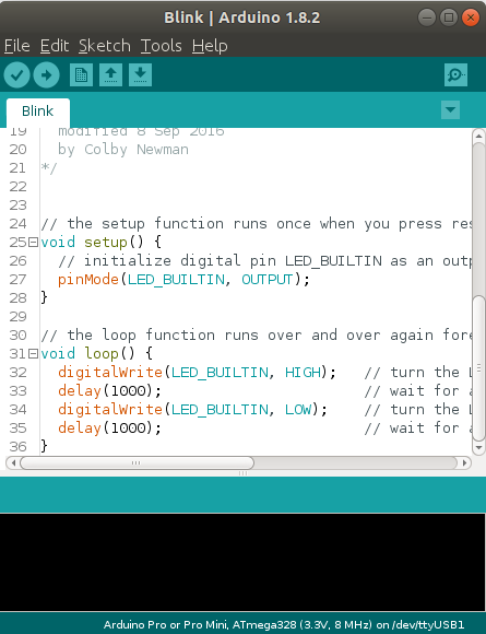
- Compatible with Arduino IDE using “Arduino Pro or Pro Mini (ATMega328 3.3V 8 MHz)” as the board option
- Microcontroller – ATMega328P-AU
- Clock – 8 MHz crystal
- Operating voltage – 3.3 V
- Ultra low power:
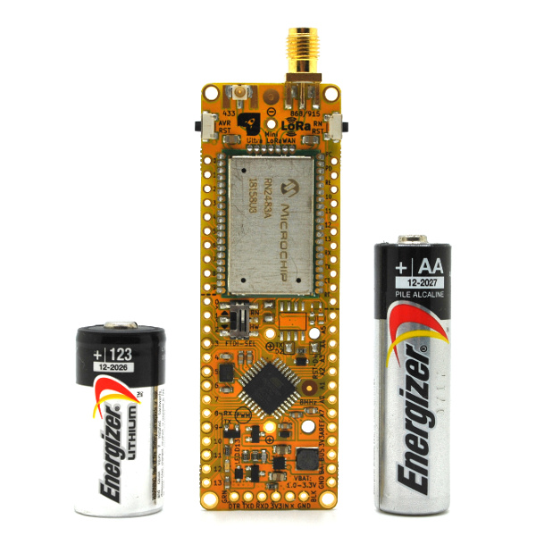
- Minimum 35.0 μA in sleep mode with a fresh 3.0 V Lithium CR123A battery
- Minimum 70.0 μA in sleep mode with a fresh 1.5 V AA battery
- Battery voltage can be as low as 1.1V (with alkaline based AA batteries, performance varies with various battery chemistry, brand, temperature and other factors)
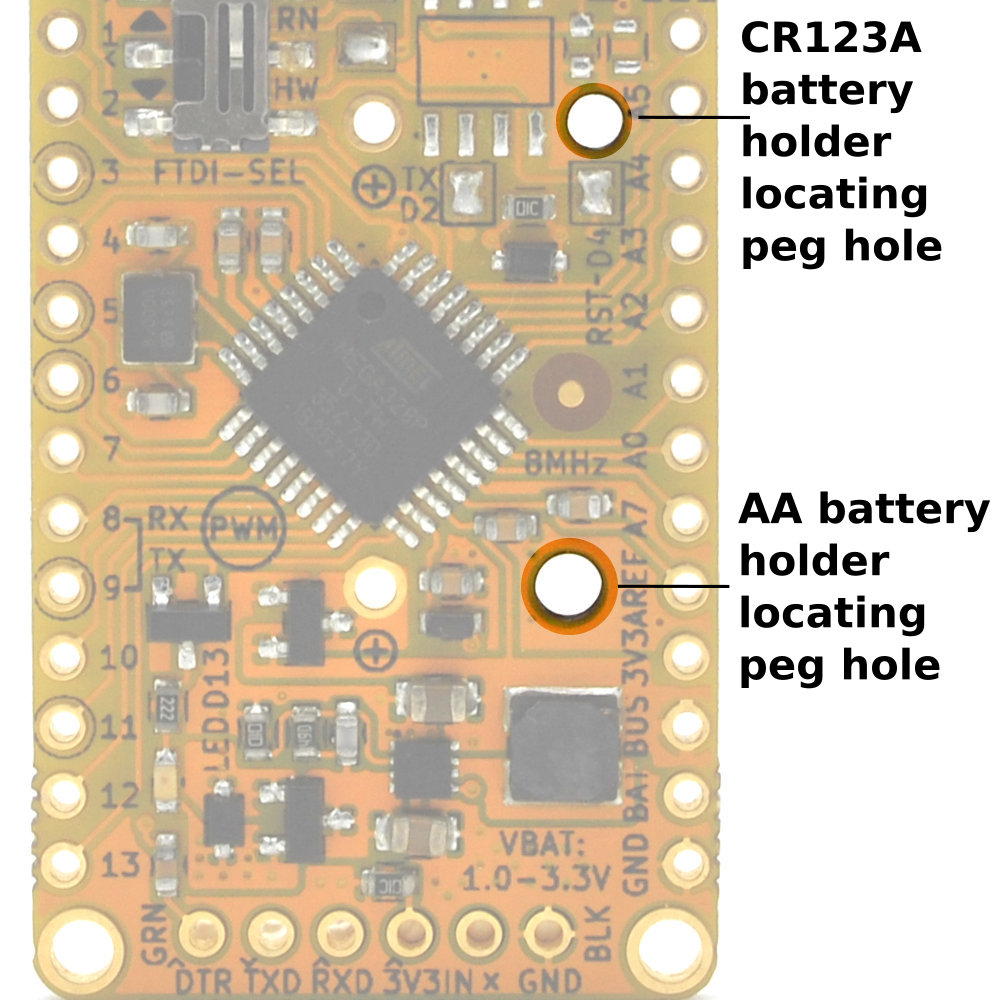
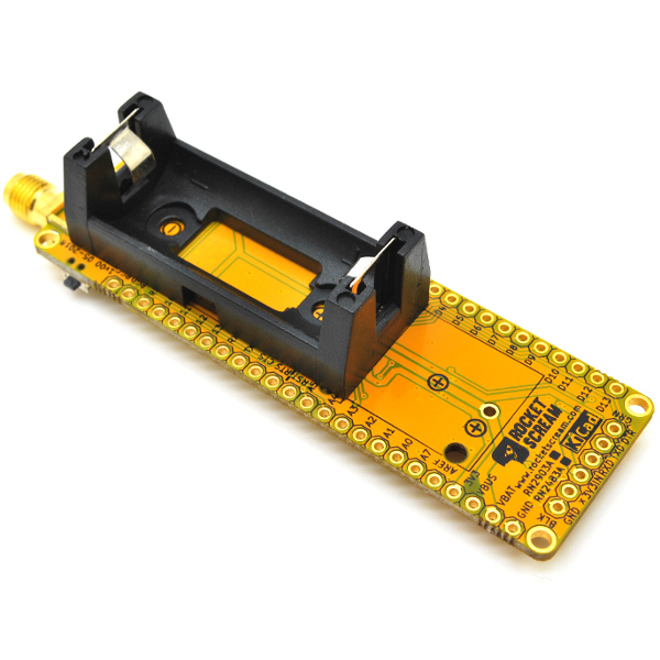
- Battery connector options – AA or CR123A battery holder but battery power can also be supplied through the breakout pins (single or dual 1.5 V batteries of any size can be used):
- Battery connector are not mounted by default even if included
- RN2483A/RN2903A can be used as a wake up source while the ATMega328P is in sleep mode
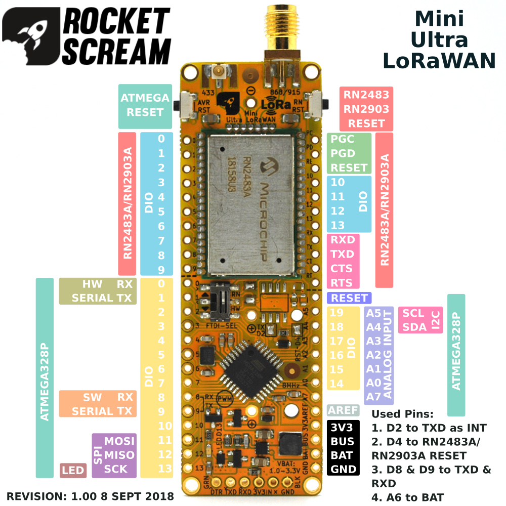
- All pins of RN2483A/RN2903A are made available on the breakout pins:
- Up to 14 digital IO pins can be used as input or output
- Battery monitoring on pin A6
- Ultra long range LoRaWAN radio module options:
- Microchip RN2483A – 868 MHz (433 MHz port are made available with u.FL connector)
- Microchip RN2903A – 915 MHz
- 2 options of antenna connector:
- SMA
- u.FL (u.FL connector is also assembled on 433 MHz port on the RN2483A version)
- Reverse battery protection
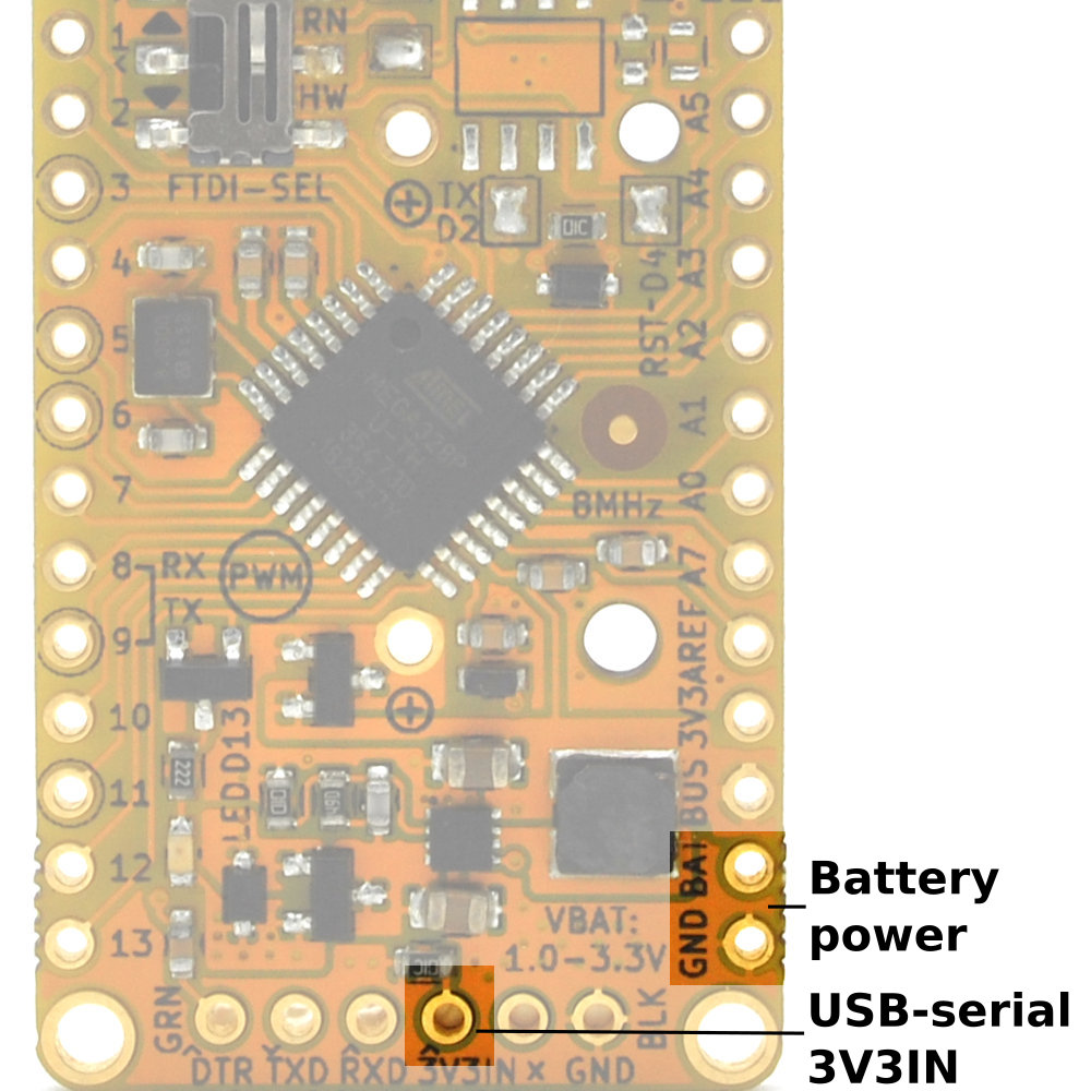
- Automatic power switch over from battery to external 3.3 V power supplied on the FTDI 6-pin header
- Indicator LED connected to digital pin 13 through a MOSFET
- ATMega328P communicates with RN2483A/RN2903A over UART through pin D8 & D9 using AltSoftSerial written by Paul Stoffregen (vs the Arduino IDE stocked SoftSerial library)
- Side reset tact switch for easy access (for both ATMega328P and RN2483A/RN2903A)
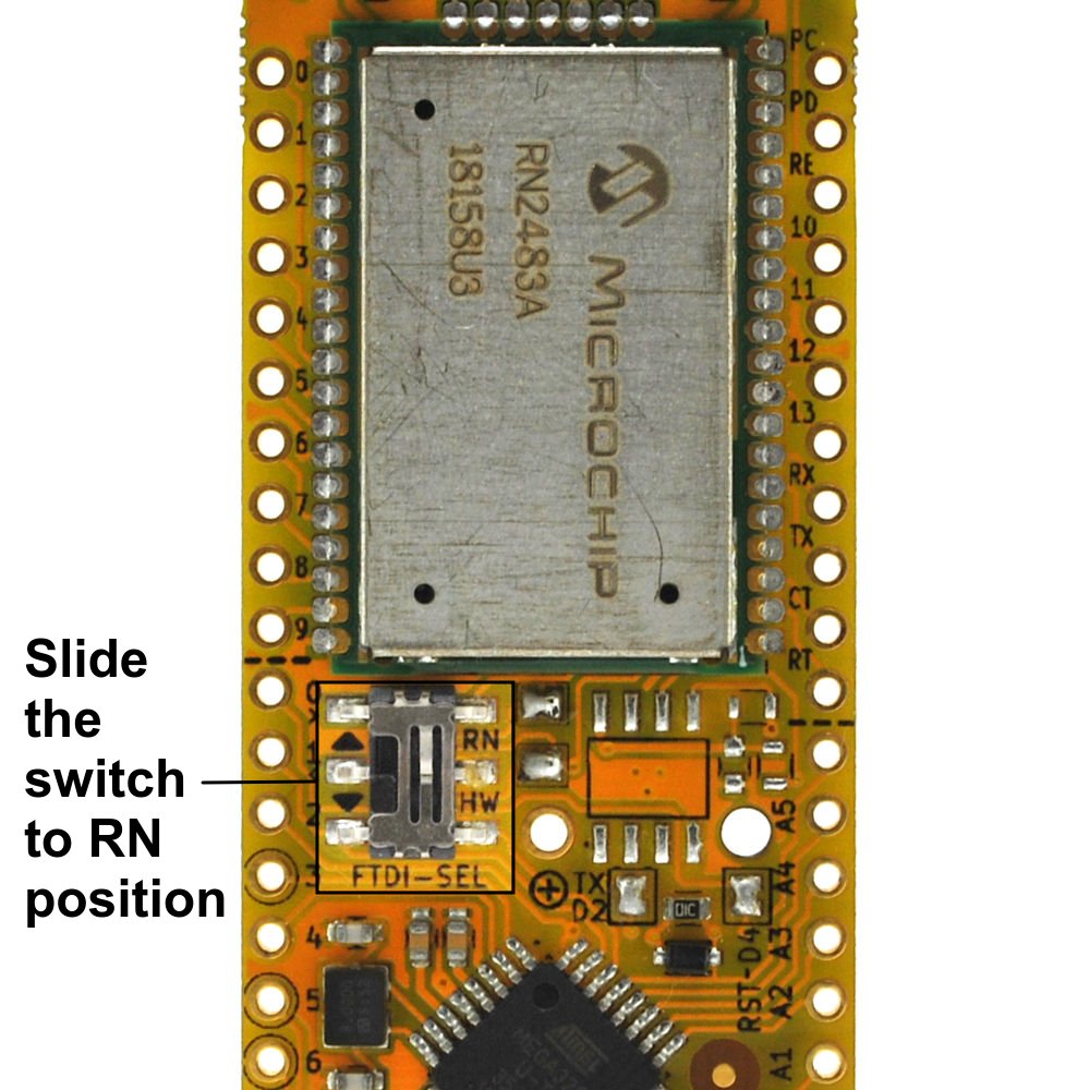
- Slide switch to isolate the RN2483A/RN2903A UART pins from the ATMega328P’s pins during RN2483A/RN2903A firmware upgrades
- FTDI USB serial 6-pin header for code upload
- Works below sub-zero temperature
- Footprint for optional encryption chip ATECC508A/ATSHA204A from Microchip that runs on the I2C bus (also fits many other memory devices that works on I2C bus)
- 900 mil in between 2 breakout headers – suitable for breadboard usage
- Dimension – 25.4 mm x 77.47 mm (1.0″ x 3.05″) (without the SMA connector)
- RoHS compliant – Yes
- Antenna not included
- FR4 TG140 PCB with ENIG surface finish
Pinout
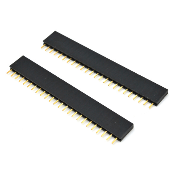
Assembly
Power Requirement

Arduino IDE Setup
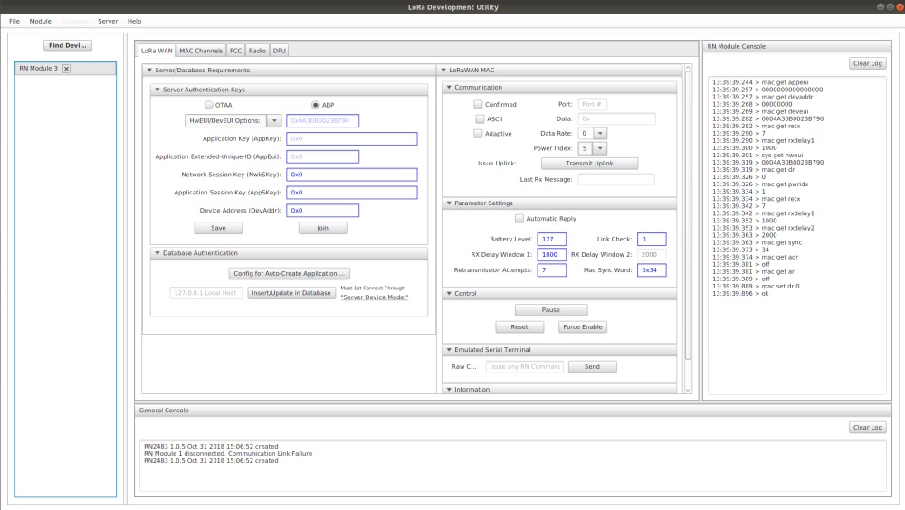
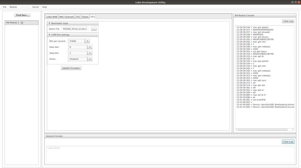
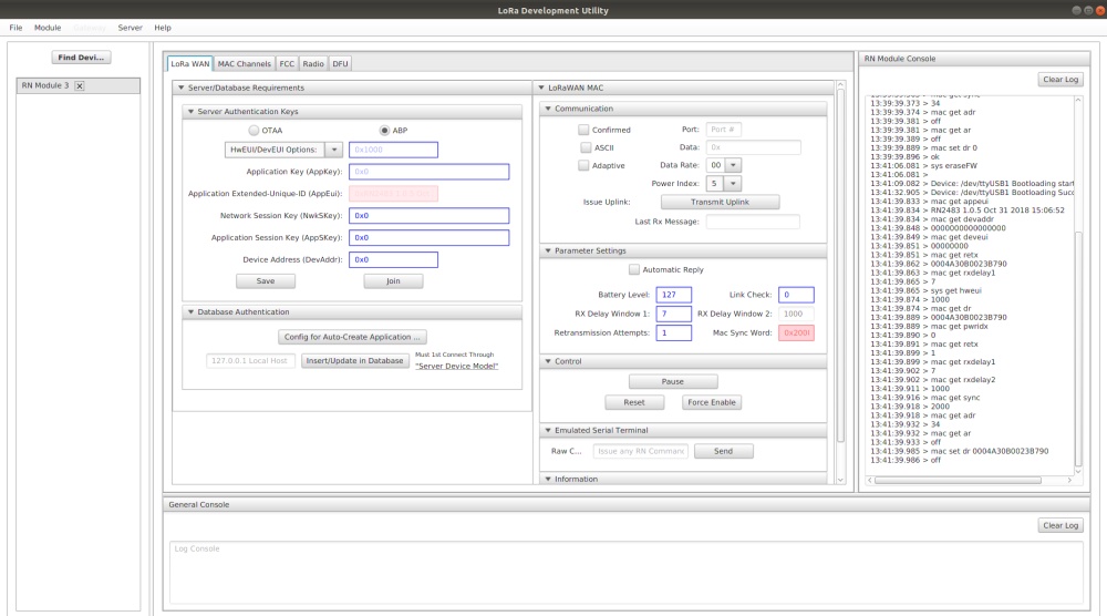
Firmware Update on Radio
Download


