
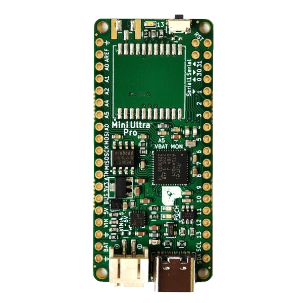
Description
Version 4 of Mini Ultra Pro! The semiconductor part shortage has drive us to revise the design to accept either a BQ24074 or BQ24075T PMIC. Both are similar PMIC but only differ in certain aspect (read below). The board has been upgraded to a 4-layer PCB for better RF and noise performance. However, parts price has increased generally across the board due to the never ending semiconductor parts shortage. Note: Current PMIC is BQ24074
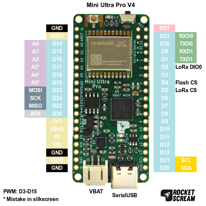
Note: There’s a mistake on the silkscreen marking on A4, A5, and A0. These should be A3, A4 & A5 just like V3.
This is our low power rendition of the Arduino Zero! We hit the limit (program flash, memory) on a custom board based on our beloved Mini Ultra 8 MHz board while doing a custom project for a client. As much as we want to make an ATMega2560 version of the Mini Ultra, the chip size (TQFP100) is just awfully too big for our liking and the price is unreasonable for an 8-bit microcontroller. In contrast, the 32-bit ARM Cortex M0+ ATSAMD21G18A provides plenty of processing power and peripherals at a reasonable cost. For the past 10 years, we have been actively involved in wireless sensor network and Mini Ultra Pro is the result of those hours and hours of developing what works in the field. This version comes WITHOUT the radio transceiver module. Specifications:
- Compatible with Arduino IDE using “Arduino/Genuino Zero (Native USB Port)” as the board option
- Microcontroller – ATSAMD21G18A-MU
- Clock – 48 MHz
- Operating voltage – 3.3 V
- Low quiescent current (1.5 μA) on-board 3.3 V 500 mA low dropout regulator
- Ultra low power – Minimum 16.5 μA (±1.0 μA) in sleep mode (known as standby mode on ATSAMD21G18A-AU) with a 3.6 V Li-Ion/Li-Pol battery as power source
- External DC source range:
- BQ24075T: 5 – 6.5 V (over voltage protection up to 28 V)
- BQ24074: 5 – 10.5 V (over voltage protection up to 28 V):
- Optimized for 6V 3W solar panel
- Battery charging management:
- Power path management for proper charging process and load balancing
- 400 mA battery charging current
- 2 indicator LED for power good and charging process indication
- PMIC differences:
- BQ24075T:
- VIN: 5 – 6.5 V (over voltage protection up to 28 V)
- VBUS output range with valid VIN: 5.5V
- BQ24074:
- VIN: 5 – 10.5 V (over voltage protection up to 28 V):
- VBUS output range with valid VIN: 4.4V
- BQ24075T:
- Suitable for battery operation (3.6 V Lithium-Ion/Polymer)
- Battery monitoring on pin A5
- On-board 2 MB (16 Mbit) serial flash for data logging:
- SerialFlash library by Paul Stoffregen is highly recommended to access the on-board serial flash
- On-chip RTC with calendar support (using the RTCZero library)
- On-board 64-bit (8-byte) unique global identifier MAC address provided by the 24AA025E64 chip:
- Has I2C address solder jumper to avoid possible same I2C address on the same I2C bus
- Yellow indicator LED connected to digital pin 13
- 500 mA fuse for USB port over current protection
- USB type-C connector with 4 through hole pegs for reliability and robust connection
- JST PH 2.0 mm battery connector for Li-Ion/Li-Pol batteries
- Side reset tact switch for easy access
- Native USB serial for code upload
- SWDIO and SWCLK of ARM Cortex SWD interface broken out on 2 2.54 mm pitch pads
- 900 mil in between 2 breakout headers – suitable for breadboard usage
- Dimension – 25.4 mm x 55.88 mm (1.0″ x 2.2″) (without the SMA connector)
- RoHS compliant – Yes
- Antenna not included
- FR4 TG150 4-layer PCB with ENIG surface finish
Documentation:








Reviews
There are no reviews yet.