• Twitter
  • Youtube
Rocket Scream
  • Blog
  • Shop
    • Arduino and Compatibles
      • Mini Ultra Series
      • osPID
    • Component
      • Connector
      • Interconnect & Cables
      • Wires
      • Sensors
        • Temperature
    • Wireless
      • Antenna
      • Module
  • Forums
  • Docs
  • Contact
  • About
  • My Account
  • Search
  • Menu Menu
  • 0Shopping Cart

Using Digital Analog Converter (DAC) on Mini Ultra Pro

You are here: Home1 / Docs2 / Using Digital Analog Converter (DAC) on Mini Ultra Pro
Overview

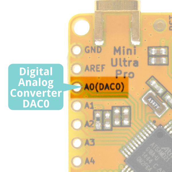
The ATSAMD21G18A-AU microcontroller on the Mini Ultra Pro comes with a built-in Digital Analog Converter (DAC) that allow it to provide analog output. Usually, when such peripheral is not available on a microcontroller, it is very common to use a resistor-capacitor filter network on a Pulse Width Modulation (PWM) output to obtain the desired analog voltage.

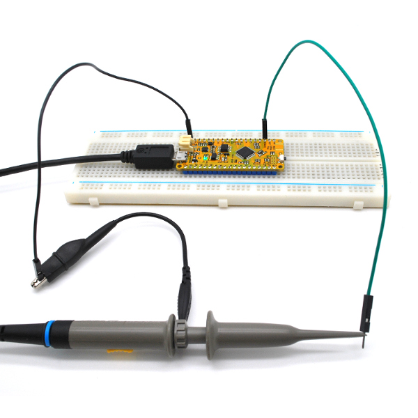
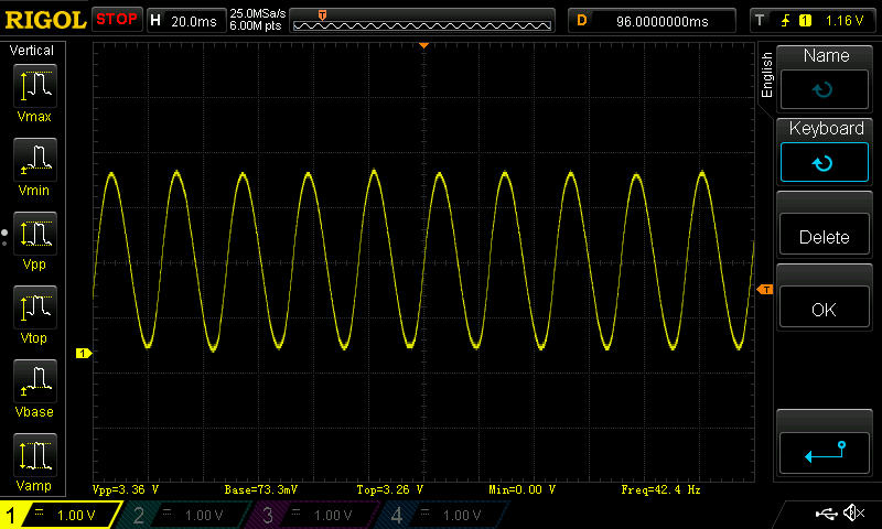
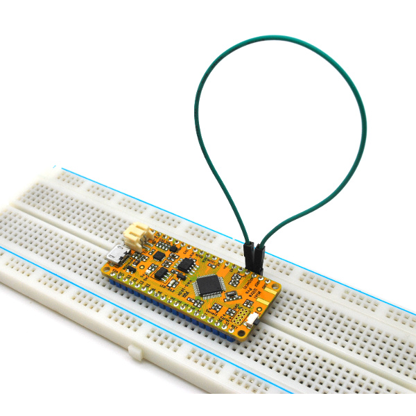
The analog voltage output is provided by DAC0 located on pin A0. Both 8-bit and 10-bit resolution is available for the analog output voltage. At 10-bit resolution setting, you would be able to output 0 to 3.3 V voltage in 1024 steps (about 3.22 mV of resolution). We found this feature to be very useful when you need to drive a sensor with a voltage reference other than your microcontroller operating voltage.

Mini Ultra Pro DAC0

Generating Analog Voltage

To demonstrate the functionality of the DAC peripheral on the Mini Ultra Pro, we will be providing a sinusoidal output voltage on pin A0 using the DAC peripheral. Use the following code and upload it onto the Mini Ultra Pro.

// ***** CONSTANTS *****
// Angle increment to sweep from -pi to +pi
const float angleDelta = 0.05;
// Midpoint of DAC value (10-bit resolution span)
const float midPoint = 1023 / 2;
const float pi = 3.142;

// ***** PIN DEFINITION *****
#define PIN_DAC0 A0

// ***** VARIABLES *****
// Argument of sin() function
float angle = 0;
// DAC value in analogWrite() function
int dacValue = 0;

void setup()
{
  // Change analog output resolution to 10-bit from default 8-bit
  analogWriteResolution(10);
}

void loop()
{
  // The sin() function returns a value between -1 & 1
  // Map -1=0; 0=1023/2; & 1:1023
  dacValue = (int)(midPoint + (midPoint * sin(angle)));

  // Increment the angle
  angle += angleDelta;

  // Wrap around the angle between -pi & +pi
  if (angle > pi)
  {
    angle = -pi;
  }

  // Generate a voltage between 0 and 3.3V.
  analogWrite(PIN_DAC0, dacValue);
}

Use an oscilloscope to probe the signal on pin A0 (DAC0).

Oscilloscope on DAC0

You should be able to get a similar waveform as below. Take note that the output swing between 0 and 3.3 V.

Sinusoidal Output DAC

However, if you do not have an access to an oscilloscope, we would be able to plot the DAC0 output voltage on your Arduino IDE. Starting from v1.6.6 of the Arduino IDE, you can visualize your data in real time graphs using the Serial Plotter feature on the IDE. In order to use the Serial Plotter, remove the oscilloscope probe and replace them with a jumper wire shorting pin A0 and pin A1. We will use the ADC on pin A1 to read the output voltage of pin A0 (DAC0).

Pin A0 Shorted to Pin A1

On top of that, we need to modify our code a little bit.

// ***** CONSTANTS *****
// Angle increment to sweep from -pi to +pi
const float angleDelta = 0.05;
// Midpoint of DAC value (10-bit resolution span)
const float midPoint = 1023 / 2;
const float pi = 3.142;

// ***** PIN DEFINITION *****
#define PIN_DAC0 A0
#define PIN_ADC A1

// ***** VARIABLES *****
// Argument of sin() function
float angle = 0;
// DAC value in analogWrite() function
int dacValue = 0;
// Voltage output of DAC0 in V
float outputVoltage = 0;

void setup()
{
  // Change analog input resolution to 12-bit from default 10-bit
  analogReadResolution(12);
  // Change analog output resolution to 10-bit from default 8-bit
  analogWriteResolution(10);
  // Wait until serial USB connection is ready
  while(!SerialUSB);
  // Set the baud rate
  SerialUSB.begin(115200);
}

void loop()
{
  // The sin() function returns a value between -1 & 1
  // Map -1=0; 0=1023/2; & 1:1023
  dacValue = (int)(midPoint + (midPoint * sin(angle)));

  // Increment the angle
  angle += angleDelta;

  // Wrap around the angle between -pi & +pi
  if (angle > pi)
  {
    angle = -pi;
  }

  // Generate a voltage between 0 and 3.3V.
  analogWrite(PIN_DAC0, dacValue);
  // Read DAC0 output and convert to 0 to 3.3 V
  outputVoltage = (analogRead(PIN_ADC) * 3.3) / 4096;
  SerialUSB.println(outputVoltage);
}

Upload the updated code to your Mini Ultra Pro and run the Serial Plotter (Tools >> Serial Plotter). You should be able to see your sinusoidal voltage output from your DAC0 of the Mini Ultra Pro!
Serial Plotter

Follow us on Twitter

Tweets by rocketscream

Subscribe to our newsletter

Information

  • About
  • Contact
  • Covid-19 Shipment Update
  • Ordering Info
  • Returns
  • Shipping Info
© Copyright - Rocket Scream Electronics
  • Twitter
  • Youtube
Mini Ultra Pro Hookup GuideUsing Real Time Clock (RTC) with Mini Ultra Pro
Scroll to top

This site uses cookies. By continuing to browse the site, you are agreeing to our use of cookies.

OK

Cookie and Privacy Settings


How we use cookies

We may request cookies to be set on your device. We use cookies to let us know when you visit our websites, how you interact with us, to enrich your user experience, and to customize your relationship with our website.

Click on the different category headings to find out more. You can also change some of your preferences. Note that blocking some types of cookies may impact your experience on our websites and the services we are able to offer.

Essential Website Cookies

These cookies are strictly necessary to provide you with services available through our website and to use some of its features.

Because these cookies are strictly necessary to deliver the website, refusing them will have impact how our site functions. You always can block or delete cookies by changing your browser settings and force blocking all cookies on this website. But this will always prompt you to accept/refuse cookies when revisiting our site.

We fully respect if you want to refuse cookies but to avoid asking you again and again kindly allow us to store a cookie for that. You are free to opt out any time or opt in for other cookies to get a better experience. If you refuse cookies we will remove all set cookies in our domain.

We provide you with a list of stored cookies on your computer in our domain so you can check what we stored. Due to security reasons we are not able to show or modify cookies from other domains. You can check these in your browser security settings.

Google Analytics Cookies

These cookies collect information that is used either in aggregate form to help us understand how our website is being used or how effective our marketing campaigns are, or to help us customize our website and application for you in order to enhance your experience.

If you do not want that we track your visit to our site you can disable tracking in your browser here:

Other external services

We also use different external services like Google Webfonts, Google Maps, and external Video providers. Since these providers may collect personal data like your IP address we allow you to block them here. Please be aware that this might heavily reduce the functionality and appearance of our site. Changes will take effect once you reload the page.

Google Webfont Settings:

Google Map Settings:

Google reCaptcha Settings:

Vimeo and Youtube video embeds:

Other cookies

The following cookies are also needed - You can choose if you want to allow them:

Privacy Policy

You can read about our cookies and privacy settings in detail on our Privacy Policy Page.

Privacy Policy
Accept settingsHide notification only