• Twitter
  • Youtube
Rocket Scream
  • Blog
  • Shop
    • Arduino and Compatibles
      • Mini Ultra Series
      • osPID
    • Component
      • Connector
      • Interconnect & Cables
      • Wires
      • Sensors
        • Temperature
    • Wireless
      • Antenna
      • Module
  • Forums
  • Docs
  • Contact
  • About
  • My Account
  • Search
  • Menu Menu
  • 0Shopping Cart

Reflow Controller Shield

You are here: Home1 / Docs2 / Reflow Controller Shield
Overview

Introduction

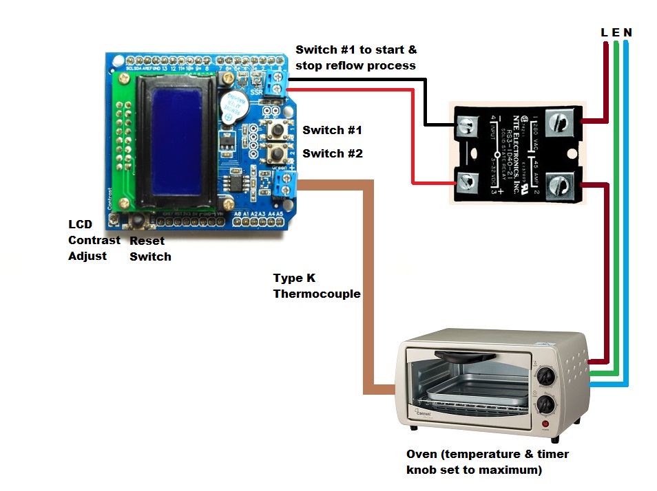
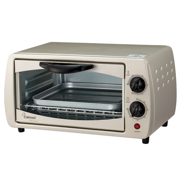
We simply can’t afford to buy an industrial reflow oven. That’s how this reflow controller shield came about. We wanted something to work without the use of a dedicated PC (and let Windows screw the reflow process by showing blue screen) and easy to use. The shield is meant to be used with an Arduino Uno or Duemilanove. An accurate thermocouple sensor interface provided by MAX31855KASA+ allows pretty accurate real time temperature acquisition. All you need is an external Solid State Relay (SSR) (rated accordingly to your oven), K type thermocouple (we recommend those with fiber glass or steel jacket), and an oven of course! We provide example code running the reflow process utilizing a PID control provided by the awesome PID library written by Brett Beauregard.

Features

  • Compatible with Arduino Uno and Duemilanove
  • Dimension avoids the shorting with the USB connector and the DC jack
  • Immersion gold finish allows easier soldering
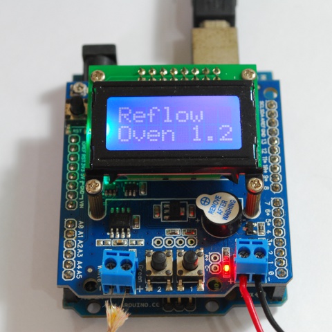
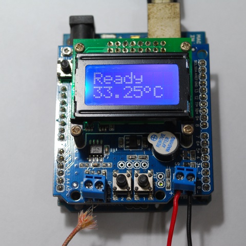
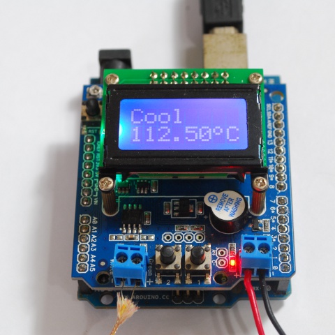
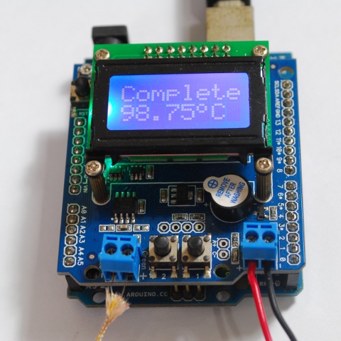
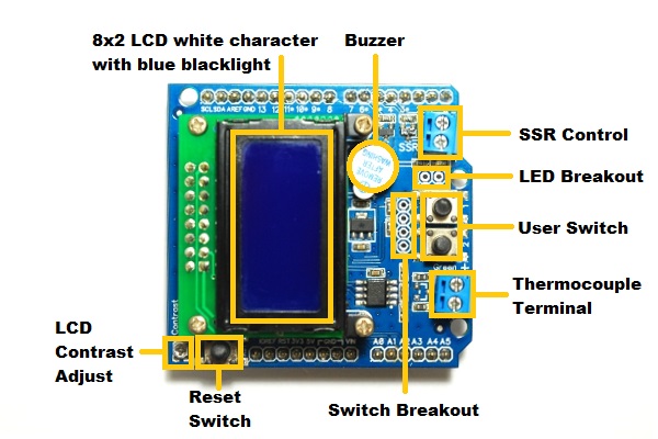
  • 8×2 LCD white character with blue back light
  • 2 push button using 1 analog pin
  • 1 red LED
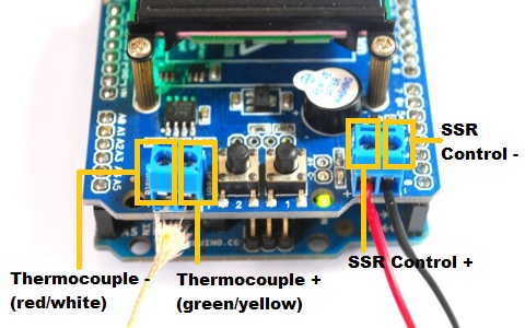
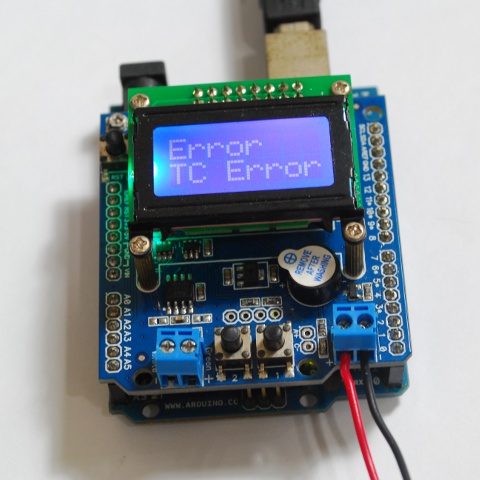
  • 1 terminal block for thermocouple
  • 1 terminal block for SSR to control heating element/oven
  • 1 buzzer with transistor for loud and annoying sound
  • 1 reset button
  • Dimension – 55.88 mm x 53.34 mm
  • RoHS compliant – Yes

Annotation

Reflow Curve Basic

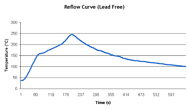
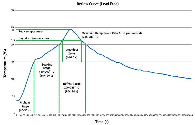
  • It is important to understand the basic profile of a reflow curve to get the best reflow result on your boards. A reflow curve can be divided into 4 four stages:
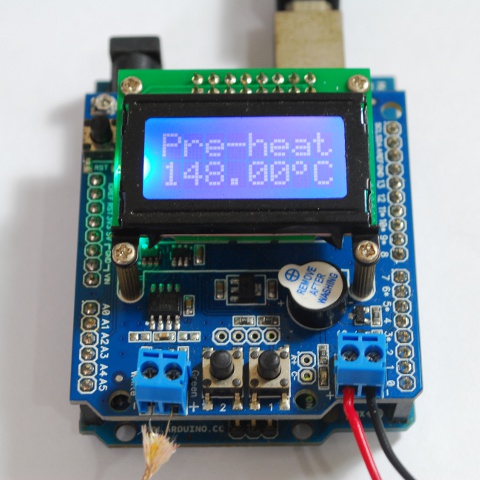
    • Preheat – The temperature is increase from room temperature to 150 °C. The ramp up rate must in between 1-3 °C per seconds. Please ensure that the ramp up rate does not exceed 3 °C per seconds as the components might experience thermal shock.
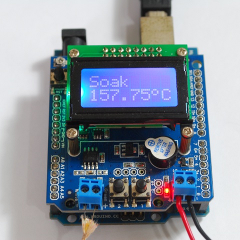
    • Soak – The soak stage serve as a solder paste oxides removal process and activating the fluxes. Whenever the temperature in this stage is too low, solder ball might form. Once reaching the 200 °C point, the board is said to have achieved a thermal equilibrium stage and ready for the next reflow stage.
    • Reflow – This stage is where the solder paste reaches the melting point at liquidous temperature which is about 218 °C for lead free solder paste (Sn-Ag-Cu based). Please ensure that the board does not stay beyond the recommended 60-90 s duration above this temperature but still adhering to the maximum 3 °C per second ramp up rate. Once the peak reflow temperature is reached, the cooling stage kicks in.
    • Cool – The cooling down stage must exhibit a ramp down rate of not more than 6 °C per seconds during the 245-200 °C range else thermal shock might occur on the components.

Reflow Curve

Achtung

This is a very dangerous project if not being handled carefully. Please take extra precaution and other safety measure when dealing with high voltage. Never ever have exposed high voltage wires lying around. It can be fatal. We would rather hear about how great your board looks like after using the reflow oven controller shield rather than anything else. Take care.

Get it

Things You Need

Item Description
Oven OvenThe oven selection is a very subjective process. We have tried a lot of oven in the past ranging from tiny 800 W to bigger ones with 1500 W output power. 2 important points:

  • The oven need to be able to heat up at a decent fast rate (2-3 °C). This is very important during the preheat stage and reflow stage. Failing to do so, the reflow curve will be very flat and you’ll end up baking the PCB longer than it supposed to be. Based on our experience, bigger oven with bigger output power does not mean it is capable of heating up quickly. As the volume of the oven gets bigger, the heating process gets pretty much slower even with higher output power.
  • The oven need to able to reach the peak temperature required for the solder paste to reflow. 250 °C should be enough to cover both lead free and leaded solder paste. The label on the oven is usually just an estimate figure, fired up the oven and measure the maximum temperature it can go.
  • Read about our oven testing experience.
Type K Thermocouple Thermocouple
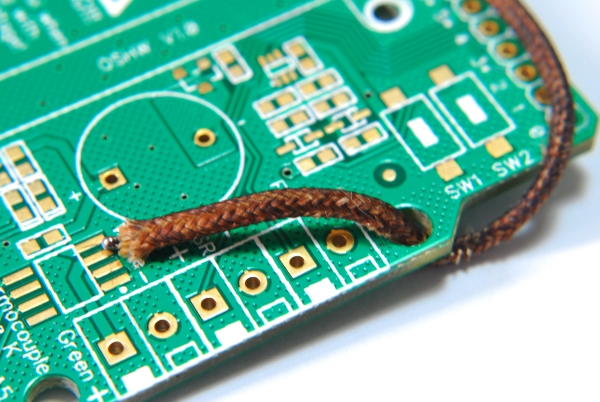
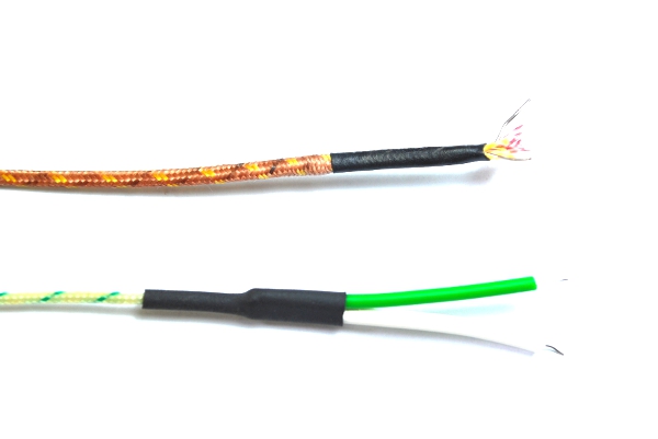
Get those with fiber glass or steel insulation jacket. Check the maximum temperature the wire can sense and we advise to choose those with higher than 500 °C. Don’t be stingy! Also take note of the maximum temperature the insulation jacket and make sure it can withstand the high reflow temperature. Recommended thermocouple includes offering from Omega. Don’t simply get some unknown thermocouple wire without any proper specifications. We are using the type K thermocouple shown below. Notice the difference of color on the insulation jacket which is based on US & Canada standard (yellow & red) and international standard (green & white). Yellow and green indicates the positive lead (Nickel – Chromium). Red and white indicates the negative lead (Nickel – Aluminium).
Solid State Relay (SSR) You’ll need an SSR with DC control voltage that can be driven directly from an Arduino pin. We are using a Crydom D2410 SSR that can drive a maximum load of 10 A with a control voltage range of 3-32 VDC. At 5 V, it requires only 5 mA to drive the control pin of the SSR. The maximum load current depends on your oven size.
Make it

Setup

  • Thermocouple Installation:
    • The location and placement of the thermocouple wire tip in the oven is crucial and important for the success of the reflow process. It is best to mount the thermocouple wire tip on a piece of extra PCB that you have like the image shown below. This PCB should be placed next to the real PCB that wanted to be assembled.Thermocouple on PCBPCB Placement
  • PCB Placement:
    • The placement of the PCB in the oven should not be directly underneath and above the heating elements of the oven.PCB Placement In Oven
  • Oven Setup:
    • There’s basically nothing to setup with the oven except putting the temperature and timer knobs to the maximum like the image below:Oven Knob
  • Arduino & Shield Setup:
    • The shield comes fully assembled except the headers. Once you have soldered the headers onto the shield and stack the shield on the Arduino board, you can connect the thermocouple wire and SSR control wires to the on board terminal block. Please ensure the polarity of the thermocouple wire (green/yellow for +, white/red for -) and also the SSR control wires are correct. If the thermocouple wires polarity is incorrect, you’ll get a reverse temperature characteristic.Terminal Block Connection
  • Sketch Upload:
    • In order to get the board up and running, you’ll need 3 firmware components:
      • Reflow example sketch: You can get the example sketch from our Github page.
      • PID Library: You can get the latest copy of the library from the Arduino playground.
      • MAX31855 Library: You can get the latest copy from our Github page. Required for board revision v1.60 and above.
      • MAX6675 Library: You can get the latest copy of the library from Adafruit’s Github page. Required for board revision v1.50 and below.
    • Do not worry too much of the PID parameters at first. We advise you to run the example sketch first without any modification before any optimization and refinement to suit your oven.
  • Final Check:
    • Before connecting the mains to the SSR, please ensure that all connections is correct and safe. There is no room for mistake as dealing with voltage can be fatal if safety precaution is not taken. Overall, your system connection will look something like the image below:Setup Connection
Run it

Up & Running

  • When the Arduino board together with the shield is being powered up, you’ll notice a splash screen indicating the firmware revision will appear on the 8×2 alphanumeric LCD. The buzzer will also beep with red LED turn on for a duration of 2 seconds.Splash Screen
  • Once the start up sequence is completed, the board will enter the idle state where it is ready to perform the reflow process. If a valid type K thermocouple wire is connected, the board will display it’s current temperature reading in Degree Celsius. You can check whether the temperature is increasing by rubbing your fingers on the tip of the thermocouple wires. If the temperature decreases when you do that, you might have connected the thermocouple wires in a reverse direction.Ready
  • When no thermocouple is connected to the board, a “TC Error” status will be displayed on the LCD. Any attempt to start the reflow process will not be executed. If you connect a thermocouple on the fly while the system is running, it will be able to detect the thermocouple wire and the error status will revert to the ready status.Thermocouple Error
  • Now we are ready make the first run of the reflow oven. We advise not to put any real board for the reflow process first except the board used for temperature monitoring. In order to check the reflow curve output of the system, connect any terminal software at 57600 bps to get the real time temperature data in the oven during the reflow process. This data can be used to plot and verify the reflow curve later on. Once everything is ready, you can press the push button “SW1” to start the reflow process. This “SW1” push button acts as a start & stop reflow process button. You’ll also notice that the red LED will start blinking at 1 second rate. If you have a terminal software running, you’ll notice the current temperature in the oven together with few other useful parameters will be sent to the computer like the screenshot below. The time and input values can be used to plot the reflow curve.Terminal
  • The whole reflow process will basically go through Preheat->Soak->Reflow->Cool sequence. All these stages is explained in the preceding sections.
  • The first stage will be the preheat stage where the temperature will be increased from room temperature to 150 °C at 1-3 °C per second rate. You’ll also notice that the current set point sent to the terminal will be 150 °C. You are only allowed to start the reflow process if the current temperature is lower than 50°C. This is to ensure that the components does not experience thermal shock if it was at room temperature prior to the process. But, you can change this temperature value in the sketch itself.Preheat
  • Once the preheat stage is completed, the process will enter the soaking stage where the temperature will be increased at a lower rate of 0.5-1.5 °C per second from 150-200 °C. You’ll notice that the set point will be increased at a 5 Degree Celcius step until it reaches 200 °C. This is to allow the temperature to rise at a less ramp compared to the preheat stage. This is an important stage which serve as a solder paste oxides removal process and to activate the fluxes.Soak
  • Once the soaking stage is completed, the process will enter the most crucial stage; reflow. Temperature will be increased from 200 °C to 245 °C at 1-3 °C per second rate. Once the peak temperature is achieved, the temperature in the oven is allowed to cool down to room temperature. You are free to open the oven door slowly to help the cooling process as long as the temperature does not decrease at a rate higher than 6 °C per second. This is important to avoid any thermal shock on the components. PID controlled oven door powered by servo motor anyone? The cooling process is deemed to be completed once it reaches 100 °C (yes, we are impatience). Once completed, a “Complete” status on the LCD will be displayed. The buzzer will also beep with the red LED on for 1 second.ReflowCoolComplete
  • Now, you can retrieve the temperature data received on the terminal and plot them to get the reflow curve. If everything goes as plan, you’ll have something like the following curve. Please ensure that the reflow curve obey all the necessary temperature increment rate and duration of each stages discussed above.Expected Reflow Curve Shape
  • However, if your reflow curve does not look like the above curve, you’ll need to do some PID parameters adjustment and tuning to make it work.
Tweak it

Tweaking the PID Parameters

The PID parameters values used in the example sketch works with most oven setup ranging from small to medium sized oven. However, it is also quite possible that it is not tuned to your setup. Some of the behavior below suggest that some parameter tweaking is required:

  • The preheat stage cannot be completed – The oven temperature hovers below the 150 °C and is unable to move to the soak stage. 
  • The soak stage temperature is increasing too fast (> 1.5 °C per seconds).
Grab it

Downloads

Reflow Controller shield is an open source hardware product.

  • Design files on GitHub

Follow us on Twitter

Tweets by rocketscream

Subscribe to our newsletter

Information

  • About
  • Contact
  • Covid-19 Shipment Update
  • Ordering Info
  • Returns
  • Shipping Info
© Copyright - Rocket Scream Electronics
  • Twitter
  • Youtube
TraLog Shield
Scroll to top

This site uses cookies. By continuing to browse the site, you are agreeing to our use of cookies.

OK

Cookie and Privacy Settings


How we use cookies

We may request cookies to be set on your device. We use cookies to let us know when you visit our websites, how you interact with us, to enrich your user experience, and to customize your relationship with our website.

Click on the different category headings to find out more. You can also change some of your preferences. Note that blocking some types of cookies may impact your experience on our websites and the services we are able to offer.

Essential Website Cookies

These cookies are strictly necessary to provide you with services available through our website and to use some of its features.

Because these cookies are strictly necessary to deliver the website, refusing them will have impact how our site functions. You always can block or delete cookies by changing your browser settings and force blocking all cookies on this website. But this will always prompt you to accept/refuse cookies when revisiting our site.

We fully respect if you want to refuse cookies but to avoid asking you again and again kindly allow us to store a cookie for that. You are free to opt out any time or opt in for other cookies to get a better experience. If you refuse cookies we will remove all set cookies in our domain.

We provide you with a list of stored cookies on your computer in our domain so you can check what we stored. Due to security reasons we are not able to show or modify cookies from other domains. You can check these in your browser security settings.

Google Analytics Cookies

These cookies collect information that is used either in aggregate form to help us understand how our website is being used or how effective our marketing campaigns are, or to help us customize our website and application for you in order to enhance your experience.

If you do not want that we track your visit to our site you can disable tracking in your browser here:

Other external services

We also use different external services like Google Webfonts, Google Maps, and external Video providers. Since these providers may collect personal data like your IP address we allow you to block them here. Please be aware that this might heavily reduce the functionality and appearance of our site. Changes will take effect once you reload the page.

Google Webfont Settings:

Google Map Settings:

Google reCaptcha Settings:

Vimeo and Youtube video embeds:

Other cookies

The following cookies are also needed - You can choose if you want to allow them:

Privacy Policy

You can read about our cookies and privacy settings in detail on our Privacy Policy Page.

Privacy Policy
Accept settingsHide notification only