New Product – FT231XS Board
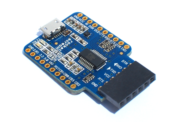
We have just released our very own version of the USB-Serial board based on the new FT231XS chip. This board went through numerous revision which initially was using the older FT232RL chip.
There might be tonnes of other similar boards out there but we think ours is the coolest among all (at least we think so).
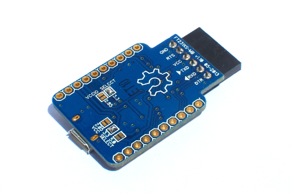
Supports 2.85 V, 3.3 V & 5 V Operation
We added a dual channel LDO allowing the board to interface with 2.85 V & 3.3 V devices. The LDO is capable of providing up to 200 mA of output current leaving you with enough head room for your target circuit. Although the FT231XS IO pins are true 3.3V CMOS drive output and TTL input, the IO pins are 5 V tolerant. You can still use them with your 5 V devices and not worry about the pins getting damaged from over voltage. The IO voltage is selectable through a solder jumper at the back of the board.
We added 2.85 V support because we prototype a lot with GSM-GPRS modules and majority of them operates at this voltage. A handful amount of GPS modules also operates at the same voltage level. This will come handy when you want to update the firmware on a GSM-GPRS module or simply want to explore AT commands directly without using a microcontroller in between.
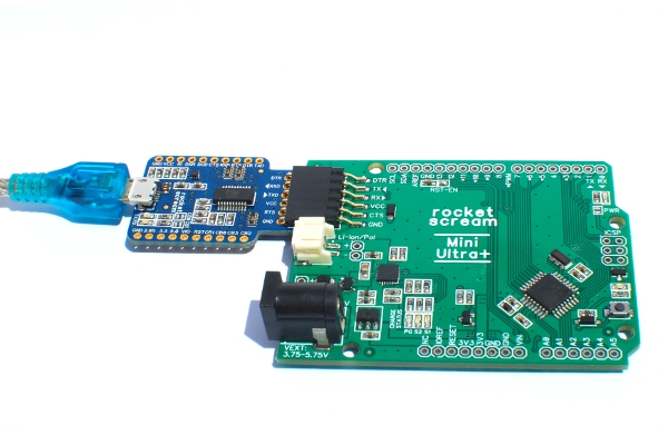
Compatible with Arduino Boards
You can use the board to upload sketches to your Arduino board (Arduino Pro, Arduino Pro Mini, Lilypad, and other Arduino compatible boards like our Mini Ultra 8 MHz and Mini Ultra Plus 8 MHz).
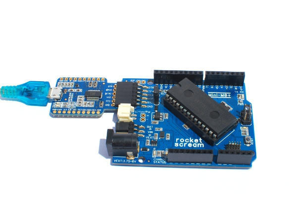
Compatible with NXP ARM LPC Series
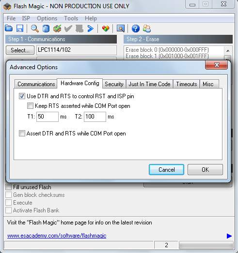
We are not a big fan of development boards that come bundled with a software development IDE. We just love to build something from scratch to pick something up. When we started exploring ARM microcontrollers (NXP’s Cortex-M0 series to be specific), we wanted something simple to upload our test firmware (rapidly and repetitive!). All NXP’s Cortex-M0 chip comes with a built-in bootloader allowing you to upload your firmware either through the UART or USB (I2C and SPI also possible) without a using programmer or debugger. We used Flash Magic to upload our firmware to our target board. Unlike an Arduino target board, NXP LPC series chip requires 2 control pins to enter into bootloading mode (reset and ISP pins) and this is made possible by using the DTR and the RTS pins on the FT231XS chip. But, you can skipped the usual 100 nF capacitor usually found installed on an Arduino board.
Here’s a custom board we made using the LPC1114FN28 ARM Cortex-M0 chip that comes in DIP28 package (wide package though!).
Using the FT231XS board with the Flash Magic software, bootloading an NXP LPC chip is awesomely reliable and very fast (auto baud rate detection). We don’t have to play around with the timing configuration and it works right out of the box!
Selectable Voltage on VCC Pin
At times, the target board may require a different voltage on the VCC pin (the 1×6 female header). You could use this voltage to step down to a voltage needed on the target board. A solder jumper is provided to select between 2.85 V, 3.3 V & and 5 V. You can opt not to provide any voltage on that pin too!
Strong USB Micro Connector
You guys must be thinking this – “Another one of those USB micro connector that would come off easily?”. We went on a long USB micro connector selection process to ensure we are getting a connector that will not come off easily. Unlike other USB micro connectors that were meant to be used with an enclosure to provide support, we chose one that comes with 4 huge mounting pads at the bottom of the connector and 2 locating pegs that are soldered to the board. Although the slot holes on the PCB cost a bit extra to manufacture, it’s better than a USB micro connector that comes off easily. We use this board quite frequently for field work and it never once came off! Furthermore, using a USB micro connector allows you to share USB cable between the board and smartphone that uses a USB micro connector.
The Usual Things
2 LED are provided for TX & RX indication with pin CBUS0 & CBUS1 configured to drive them respectively. All pins are broken out to 2 rows of standard 0.1″ spacing header which also includes the pins that are already provided on the 1×6 female header. You could use the IO on the FT231XS for bit banging application. Board comes with ENIG surface finish for easy soldering and pre-configured to 3.3 V VCCIO and 3.3 V on the VCC pin (1×6 female header).
The FT231XS Board is on sale now in small quantity!
Happy tinkering!


Leave a Reply
Want to join the discussion?Feel free to contribute!